Continue to Site

Eng-Tips is the largest engineering community on the Internet

Intelligent Work Forums for Engineering Professionals

  • Congratulations KootK on being selected by the Eng-Tips community for having the most helpful posts in the forums last week. Way to Go!

Pre-Engineered Canopy Reactions Forces for a Mat Foundation (Also includes equipment skids) 1

Status
Not open for further replies.

oengineer

Structural
Apr 25, 2011
708
I am working on the design of a Mat Foundation. The Mat foundation is supporting 4 large equipment skids and a Pre-Engineered Canopy. The Canopy is composed of 12 columns with a rain skirt roof.

This link contains a sketch of what the project looks like:

The canopy will not have a siding, just columns and a 3’ rain skirt at the top of the prefab building.

I cannot obtain the loads for the pre-engineered canopy from the manufacturer because it will be going out to bid and they cannot specify the building manufacturer. So I have to calculate the lateral reaction loads for the pre-engineered canopy (i.e. wind lateral reactions & dead lateral reactions)


I have some questions:

[ul]
[li]How would one go about to determine the lateral dead load for a pre-engineered building/canopy? Are there any technical guides that give examples of this?[/li]
[/ul]


[ul]
[li]How would one go about to determine the lateral wind load for a pre-engineered building/canopy? Are there any technical guides that give examples of this? I ask because pre-engineered metal buildings typically have much greater wind forces at their reactions than a conventional steel building. [/li]
[/ul]


[ul]
[li]Would hairpins still be necessary for a Mat Foundation supporting a pre-engineered building/canopy at the column supports?[/li]


[/ul]

[ul]
[li]Are there any potential issues to consider/beware of for using a mat foundation to support a pre-engineered metal canopy?[/li]
[/ul]


Suggestions/comments are appreciated.
 
Replies continue below

Recommended for you

Is there any bracing expected with this structure? Portal frames one way/tie rods the other way?

Not knowing many additional particulars, I took a stab at your questions below:

-I don't understand what you mean by lateral dead loads.

-Looks to me like this would be a standard open building designed under ASCE 7, and I'd think that wind uplift on the roof will probably control your anchorage design. Unless this thing is heavier than it looks and you're in a very high seismic region.

-Depends on what your anchor reaction forces are, what your edge distance is, and how deep your mat footing is. It seems likely to me that you could avoid them unless your edge distance is very small.

-Depending on what kind of equipment it is, it seems likely that mat will be sized based on that and you'll have plenty of capacity and anchorage depth for your relatively lightly loaded canopy columns.
 
strucbells said:
Is there any bracing expected with this structure? Portal frames one way/tie rods the other way?

To be honest, I don't know. Their may be trusses in the roof skirt, but I don't think there will be any on the columns. I cannot obtain the vendor drawings for the pre-engineered canopy, so I won't know for sure.

I don't understand what you mean by lateral dead loads.

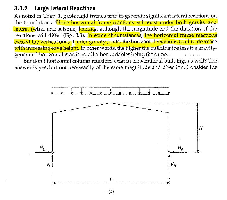
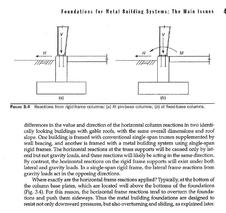
The images below are from the Foundation and Anchor Design Guide for Metal Building Systems book
pre-eng_horiz_rf6qfu.jpg

pre-eng_horiz_2_mtlvkn.jpg


-Looks to me like this would be a standard open building designed under ASCE 7, and I'd think that wind uplift on the roof will probably control your anchorage design. Unless this thing is heavier than it looks and you're in a very high seismic region.

In the past when I have designed foundations for pre-engineered metal buildings their horizontal reaction forces were greater than anything i ever came across in typical conventional steel building. Regarding the wind uplift playing a significant role of the anchorage design,you are probably correct.

-Depends on what your anchor reaction forces are, what your edge distance is, and how deep your mat footing is. It seems likely to me that you could avoid them unless your edge distance is very small.

I am hoping to use either 6 inches or even 12 inches from the edge of the mat foundation to the nearest anchor bolt center-line, for the edge distance.

-Depending on what kind of equipment it is, it seems likely that mat will be sized based on that and you'll have plenty of capacity and anchorage depth for your relatively lightly loaded canopy columns.

The equipment skid are the largest weight on the proposed mat foundation. I am certain that they will govern, but I want to consider the effects of the pre-engineered canopy on the mat foundation, as well. I have only ever designed pre-engineered buildings for Slab-on-grade foundations supported by ether drilled piers or spread footings. I don't believe a mat foundation would have a problem, but I just wanted to get some thoughts on the matter in case I am overlooking something.
 
Simple notes for you to consider:

1) Use ASCE wind load for open buildings. I believe the lowest wind speed used by PEBM is 100 mph, so the high reaction for many regions with lower wind speed (this is a standard practice, for efficiency on cost control, they don't like to change).
2) Calculate wind load on moment frame in short direction.
3) Calculate wind load on braced frame in long direction.
4) Combine loads obtained from 2 & 3 above, this is the design wind load.
5) you can add estimate weight of the structure to reduce wind effect, or conservatively ignore for the preliminary design.

Building weight is absolutely essential for seismic design. The design steps will be similar. Shear pin is required when column subjects to high tensile force.
 
retired13 said:
1) Use ASCE wind load for open buildings. I believe the lowest wind speed used by PEBM is 100 mph, so the high reaction for many regions with lower wind speed (this is a standard practice, for efficiency on cost control, they don't like to change).
2) Calculate wind load on moment frame in short direction.
3) Calculate wind load on braced frame in long direction.
4) Combine loads obtained from 2 & 3 above, this is the design wind load.

Okay, I am using ASCE 7 for the design of the pre-engineered canopy. Just wanted to verify that the calculation of the wind load on the pre-engineered canopy is the mainly the same procedure as it would be for a conventional steel building.

Do you have any knowledge on determining the horizontal dead load applied to support reactions for pre-engineered canopies/buildings?
 
I have been in a similar situation to you in the past. Where the contractor needs a foundation design prior for bidding purposes prior to even going out to bid with a metal building. I don't get too worked up about those situations. I do my best to take a stab at the foundation design and just try to be conservative. I then make sure it's known that I need to adjust the designs once the metal building reactions are provided. You can estimate the loads using a simple program like RISA or whatever you have.

For dead, live and snow loads you can ballpark the thrust at the base of the clear span frame by using (W*L^2/12)/(distance from column base to eave - 1'-0"). This should get you somewhat close.

Your instance might be a little different as you are designing a mat foundation. My typical metal building foundation is a spread footing type foundation. FWIW, I specifically exclude preliminary metal building foundation design in my proposals to avoid doing the project twice. Occasionally I am asked to help with preliminary design up front. In these instances I will typically increase my proposal accordingly.
 
SteelPE said:
I have been in a similar situation to you in the past. Where the contractor needs a foundation design prior for bidding purposes prior to even going out to bid with a metal building. I don't get too worked up about those situations. I do my best to take a stab at the foundation design and just try to be conservative. I then make sure it's known that I need to adjust the designs once the metal building reactions are provided. You can estimate the loads using a simple program like RISA or whatever you have.

For dead, live and snow loads you can ballpark the thrust at the base of the clear span frame by using (W*L^2/12)/(distance from column base to eave - 1'-0"). This should get you somewhat close.

Your instance might be a little different as you are designing a mat foundation. My typical metal building foundation is a spread footing type foundation. FWIW, I specifically exclude preliminary metal building foundation design in my proposals to avoid doing the project twice. Occasionally I am asked to help with preliminary design up front. In these instances I will typically increase my proposal accordingly.


Alright, this is good to know.

I have been reading through the Foundation and Anchor Design Guide for Metal Building Systems and it appears the Appendix called "Frame Reaction Tables" talks about reactions to be used for the situation that i am in and what you described.

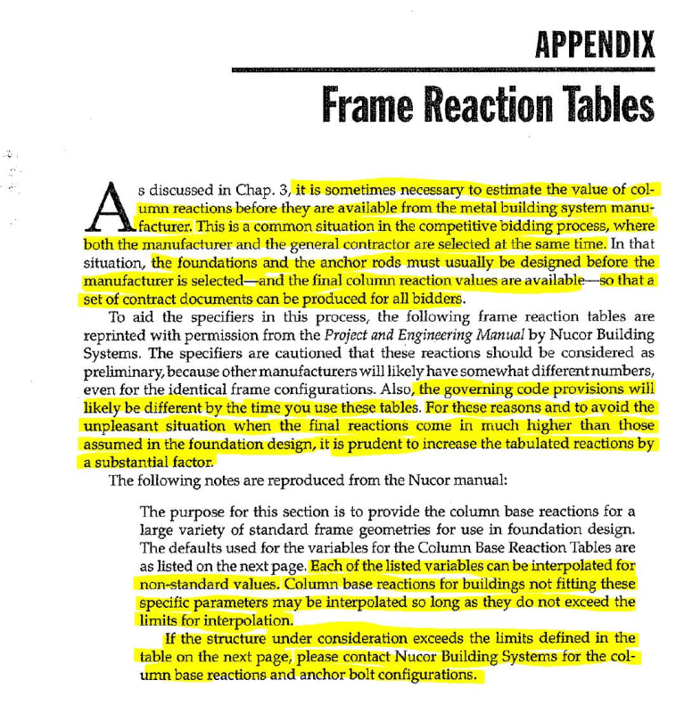
Here is what the Foundation and Anchor Design Guide for Metal Building Systems says on the subject:
pre-engineered_column_reactions_fqalon.jpg
 
Can anyone comment on experience using the information I mentioned form the Foundation and Anchor Design Guide for Metal Building Systems book, regarding the column reactions?
 
oengineer,

1) The lateral loads come from wind for open structures, including wind on exposed equipment, and seismic inertia forces. See ASCE7 for details.
2) Support reactions are derived by perform analysis on framing system described in my previous response. The reactions are utilized to determine the thickness of the mat foundation. For your case, I think uplift will be critical, so have a quick check/estimate the anchorage requirement, mainly anchor bolt embedment length. You might need to deepen the edges of the mat to accommodate the bolts.
 
You know the general geometry of the frame, frame spacing, and the loading I presume? Why not run a simple frame analysis using some assumptions from past projects regarding frame dimensions? It is not exact, but it will be close. The good contractors doing this type of work know how to include allowances for changes after or are skilled at defining what they did/did not include.
 
Here's a good article about foundation types for PEMBs from the author of your book: Link
 
retired13 said:
oengineer,

1) The lateral loads come from wind for open structures, including wind on exposed equipment, and seismic inertia forces. See ASCE7 for details.
2) Support reactions are derived by perform analysis on framing system described in my previous response. The reactions are utilized to determine the thickness of the mat foundation. For your case, I think uplift will be critical, so have a quick check/estimate the anchorage requirement, mainly anchor bolt embedment length. You might need to deepen the edges of the mat to accommodate the bolts.

This foundation will be located in a Non-seismic area. I do not have any available information on the pre-engineered canopy, besides what is shown in the sketch in the link of this original post.

I plan on making the entire Mat Foundation 2'-6" thick. I believe this should be enough thickness to embed the anchor bolts for the canopy & the equipment skids.
 
Brad805 said:
You know the general geometry of the frame, frame spacing, and the loading I presume? Why not run a simple frame analysis using some assumptions from past projects regarding frame dimensions? It is not exact, but it will be close. The good contractors doing this type of work know how to include allowances for changes after or are skilled at defining what they did/did not include.

When you talk about "frame", I assume you mean the Pre-engineered canopy? If so, I know the geometry, I know the weight of the roof skirt, I know the wind speed of the area and can determine the wind loads based on that, but i do not know the weight of the steel columns. I imagine that the weight of the canopy will not govern the mat foundation design, but I will need all the column reactions to design the anchor bolts for the columns.

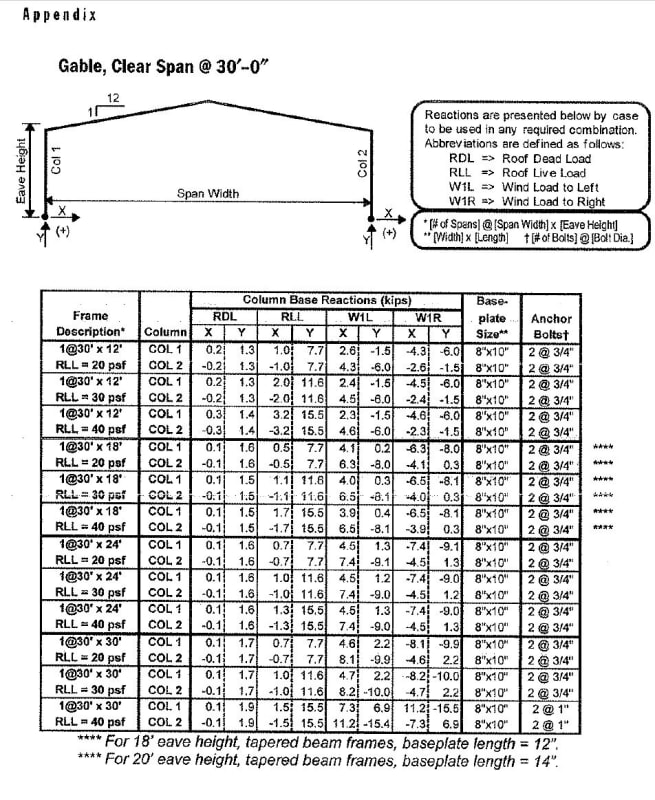
The Appendix in Foundation and Anchor Design Guide for Metal Building Systems book gives some preliminary values for the horizontal dead load reactions:

pre-engineered_column_reactions_2_yokjju.jpg


It also talks about modifying the values, as well.

I am not aware of a past project i could reference for this particular situation I am currently dealing with.
 
I agree with the 5 steps suggested earlier by @retired13
You have the overall building size and bay spacing. Assume a reasonable framing member size and proceed with the 2D analysis along transverse (moment frame) and longitudinal (Braced frame, say in 1 or 2 bays)directions.
Based on your bay spacing, you can run two typ. interior frames in the transverse direction to account for the different tributary widths and one along the longitudinal direction. Consider the results from the runs to estimate the max. reactions at various column bases.
The primary aim is to get a preliminary (slightly conservative) design for the foundation and anchors, so that the GC has something to estimate the quantity for bid.
Once the project is in construction and a Pre-engineered building contractor is selected, they will run their design and provide you with reactions at the base. The numbers you estimated during design should be in the ball-park to avoid a significant redesign of things at this stage.

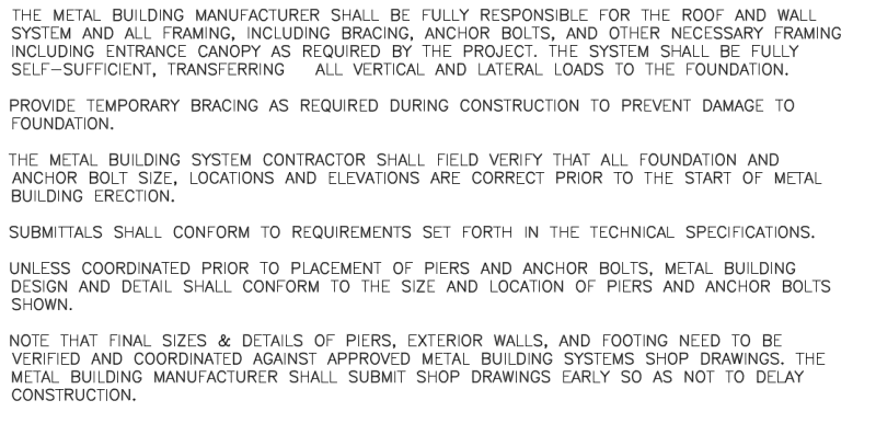
I usually add some notes on the drawings to cover the requirements:

Untitled_qmuwzn.png


During construction,we had to sometimes push the GC to get us the reactions from the Pre-engineered building contractor ahead of time so that we can review them and make any changes to the foundations if required, prior to approving rebar shops.
 
If it were me for this preliminary stage I'd either design the anchor bolts for tension for the full wind uplift (ignoring dead load of the frame) or assume some small nominal dead load. The article I linked estimates 2-5 PSF for DL for single story PEMBs. Yours may be even lighter due to the lack of siding. Depends how much time & budget you have to complete the exercise.

For anchor bolt shear, it seems you have everything that you need in the table above. Interpolate the estimated horizontal dead load reactions for your geometry and multiply up by some "factor of safety" you feel comfortable with (as discussed in the document you linked) & add in your calculated wind loads (since your frame won't have the full siding load included in this table).

You'll have to pick an appropriate edge distance for concrete breakout unless you plan on using anchor reinforcement.

For a 2'-6" deep mat foundation, generally it seems to me that this structure will be like a flea on its back if it has minimum reinforcing at top and bottom mats. For uplift you can calculate how much tributary slab area you need to pick up and check the resulting flexure in your mat. Again, for a 2'-6" thick mat, seems like this shouldn't be hard to make work.

You should be able to finalize your design later once you get the actual reactions so as long as you are in the ballpark and conservative, you should be ok.
 
I agree with stucbells regarding the foundation. I have never used a mat foundation for this type of problem, but I assume there must be a geotech reason to do so.

I would use typical rolled sections in the frame analysis, a typical cladding mass, and your reactions should work out conservative. We also work with many pre-eng guys that will crank out preliminary reactions if you float the idea they will get to bid. We will typically use a 10-25% allowance at this stage. How to select that value depends on how well we know the parties.
 
Brad805 said:
I agree with stucbells regarding the foundation. I have never used a mat foundation for this type of problem, but I assume there must be a geotech reason to do so.

I would use typical rolled sections in the frame analysis, a typical cladding mass, and your reactions should work out conservative. We also work with many pre-eng guys that will crank out preliminary reactions if you float the idea they will get to bid. We will typically use a 10-25% allowance at this stage. How to select that value depends on how well we know the parties.

The reason I am using a Mat foundation is for the @ equipment skids located under the canopy (see link: )

The foot print of the equipment skid is as shown in the image below:

skid_layout_1_ttviol.jpg


[ADD] THE SKID FOOT PRINT IS 770" X 137".

The elevation view of the equipment skid is as shown in the image below:

skid_layout_2_juu9mn.jpg


[ADD] THE HEIGHT OF THE EQUIPMENT IS 128".

As you can see from the elevation and plan view the equipment skid will be rather large. There are 2 of these skids contained inside the canopy. The skid shown has a total operating weight of 40 kips.

I have never heard of a equipment skid supported on a slab-on-grade w/grade beam foundation, so i believe that a mat foundation would be appropriate. I then obtained parameters to design a mat foundation from the geotechnical engineer.

I would think that a thick Mat foundation would allow for all anchor bolts to be installed with enough embedment.

Please let me know if there is another way to go about this.
 
Those are not very heavy skids. It looks to me they need roughly 16 bearing points per skid. If the skid vendor has indicated the bearing points one could conceivably install on pad/piers, but if you have poor soils the mat fdn will perform much better. I assume the skids are elevated off the slab.

If your client is okay with the mat foundation, and would like the option for heavy loads in the future, by all means, that is a great design. We have seen many thickened edge slabs for this type of application as well.
 
Brad805 said:
Those are not very heavy skids. It looks to me they need roughly 16 bearing points per skid. If the skid vendor has indicated the bearing points one could conceivably install on pad/piers, but if you have poor soils the mat fdn will perform much better. I assume the skids are elevated off the slab.

If your client is okay with the mat foundation, and would like the option for heavy loads in the future, by all means, that is a great design. We have seen many thickened edge slabs for this type of application as well.

The skid will be bearing on top of the slab/mat foundation. The equipment skid needs to 6" above the grade. The geotech engineer recommends that the min depth below grade for the mat foundation be 2'-0". Thus the reason for the 2'-6" thick mat foundation.

If pad/piers are provided at all the anchor bolt locations of the skid, then that would mean that the skid framing needs to be designed to span from pad/piers to pad/piers, correct?

Also, wouldn't using pad/piers for all the equipment skid anchorage locations & canopy locations be more labor intensive to construct?

I would also think a slab (if not a mat foundation) would be needed to transfer loads from the hairpins for the pre-engineered canopy to the foundation.

Thoughts/comments?
 
Status
Not open for further replies.

Part and Inventory Search

Sponsor