Continue to Site

Eng-Tips is the largest engineering community on the Internet

Intelligent Work Forums for Engineering Professionals

  • Congratulations GregLocock on being selected by the Eng-Tips community for having the most helpful posts in the forums last week. Way to Go!

Pre-Engineered Canopy Reactions Forces for a Mat Foundation (Also includes equipment skids) 1

Status
Not open for further replies.

oengineer

Structural
Apr 25, 2011
708
I am working on the design of a Mat Foundation. The Mat foundation is supporting 4 large equipment skids and a Pre-Engineered Canopy. The Canopy is composed of 12 columns with a rain skirt roof.

This link contains a sketch of what the project looks like:

The canopy will not have a siding, just columns and a 3’ rain skirt at the top of the prefab building.

I cannot obtain the loads for the pre-engineered canopy from the manufacturer because it will be going out to bid and they cannot specify the building manufacturer. So I have to calculate the lateral reaction loads for the pre-engineered canopy (i.e. wind lateral reactions & dead lateral reactions)


I have some questions:

[ul]
[li]How would one go about to determine the lateral dead load for a pre-engineered building/canopy? Are there any technical guides that give examples of this?[/li]
[/ul]


[ul]
[li]How would one go about to determine the lateral wind load for a pre-engineered building/canopy? Are there any technical guides that give examples of this? I ask because pre-engineered metal buildings typically have much greater wind forces at their reactions than a conventional steel building. [/li]
[/ul]


[ul]
[li]Would hairpins still be necessary for a Mat Foundation supporting a pre-engineered building/canopy at the column supports?[/li]


[/ul]

[ul]
[li]Are there any potential issues to consider/beware of for using a mat foundation to support a pre-engineered metal canopy?[/li]
[/ul]


Suggestions/comments are appreciated.
 
Replies continue below

Recommended for you

KootK said:
I'm reading that the other way. When you have the bypass condition, which you may well, the slab haunch is okay.

How would the pre-engneered canopy have girt inset if there is no siding on the pre-engineered canopy?
 
oengineer,

For your application, either mat or mat with down turn will work. The former will raise the bid price a little because the volume of concrete. The mat with down turn might save a little concrete, but the work is more tedious, including the effort required now to get the size and thickness in the ball park. I suggest to perform analysis on an interior frame for the case of wind and dead weight of the roof to get an estimate uplift force, and use that to estimate the required size and embedment length of anchor bolts. From that, you can be more confident on what is the mat thickness to use.
 
retired13 said:
I suggest to perform analysis on an interior frame for the case of wind and dead weight of the roof to get an estimate uplift force, and use that to estimate the required size and embedment length of anchor bolts.

I second this. For canopies wind uplift is critical. You'll need to make sure the mat/haunch has enough ballast to resist the uplift. You'll also need an estimate of the downward forces to determine the width of the haunch or the mat fdn thickness. You'll also need to make sure you have enough sliding resistance (either with passive pressure using the haunch or friction with a mat foundation).

oengineer said:
How would the pre-engneered canopy have girt inset if there is no siding on the pre-engineered canopy?

If it's just a canopy you won't have girts.
 
You are worrying about many of the wrong things. Lean more on logic and judgment and less on cookbooks.

The "cookbook" bit about the girts has nothing to do with whether or not a haunch can "work". Almost anything can be made to work.

The book's author knows that it is inefficient to have the column anchor bolts too close to a free edge. IF you have siding and girts to grade and IF you set the edge of the footing on the girt line and IF the girts frame into the column rather than pass by, the column anchor bolts will LIKELY be too close to the edge of the "haunch" footing. Bolt pullout/breakout MIGHT be a problem and the load on the footing MIGHT be too eccentric to be efficient.

You don't have girts OR siding, so your foundation edge can be anywhere you want it to be. You are not confined to putting the foundation edge at the girt line because you don't have a girt line at grade.

You will need to make revisions once the PEMB guy gets involved. There is no way around this. His anchor bolt sizes and patterns will be different than your guesses. He might even want to increase the building's efficiency by using his standard components and lengths (i.e. 20' column centers instead of 17' and 12' as you have it). You might not like his column proximity to your equipment once everything is sized and the overall width might grow just a little.

If it were me, I'd ditch the PEMB, conventionally frame it (giving you capacity to support the inevitable hanging process pipes), single-slope it, gutter one side, lose the rigid frames, find a place for eccentric bracing on four sides, pin the column bases, design individual column footings, and set the skids on their own thickened slabs.


retired13 said:
For your application, either mat or mat with down turn will work. The former will raise the bid price a little because the volume of concrete. The mat with down turn might save a little concrete, but the work is more tedious, including the effort required now to get the size and thickness in the ball park. I suggest to perform analysis on an interior frame for the case of wind and dead weight of the roof to get an estimate uplift force, and use that to estimate the required size and embedment length of anchor bolts. From that, you can be more confident on what is the mat thickness to use.


I had a discussion with a Construction Project Manager about the Mat vs Downturn slab for this situation. He said that the Downturn slab can be economical because (and I am paraphrasing) the construction crew would be doing about the same amount of worrk to construct either foundation, but essentially your bringing a whole lot of material that is not required. He mentioned that that the saving in labor for the mat vs the downturn slab would probably be very minimal and that the cost of material would mainly govern.


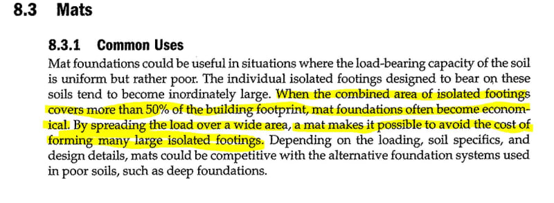
I then showed the Construction Project Manager the image below:


mat_econ_adlm21.jpg


After seeing this the Construction Project Manager said it would depend on the size of the haunches for the slab.


Currently I have a haunch that is 6 ft long x 5 ft wide x 3 ft tall/high. The grade beams connected to it are 3'-8" ft wide x 3 ft tall/high (the grade beam is being considered to help resist the wind uplift). The slab will be 18" thick due to the anchorage of the skids (I have not been provided the location of the anchorage for the skids).

The center line of the pre-engineered canopy columns from the edge of the foundation is 1'-7 1/2" (this is without knowing the configuration of the canopy column).

Based on the following post in this thread I fell much more comfortable using the Downturn Foundation instead of a Mat Foundation (see quotes below):

JLNJ said:
The "cookbook" bit about the girts has nothing to do with whether or not a haunch can "work". Almost anything can be made to work.

The book's author knows that it is inefficient to have the column anchor bolts too close to a free edge. IF you have siding and girts to grade and IF you set the edge of the footing on the girt line and IF the girts frame into the column rather than pass by, the column anchor bolts will LIKELY be too close to the edge of the "haunch" footing. Bolt pullout/breakout MIGHT be a problem and the load on the footing MIGHT be too eccentric to be efficient.

You don't have girts OR siding, so your foundation edge can be anywhere you want it to be. You are not confined to putting the foundation edge at the girt line because you don't have a girt line at grade.

retired13 said:
For your application, either mat or mat with down turn will work. The former will raise the bid price a little because the volume of concrete. The mat with down turn might save a little concrete, but the work is more tedious, including the effort required now to get the size and thickness in the ball park.

I have run the calculations for the uplift acting on the haunch for "DL+WL" and the haunch, slab, & grade beam check out.

Are there any other items recommended to look into regarding this design situation?
 
Also, would the use of hairpins to help resist lateral loads to the anchor bolt be beneficial in this situation?

Since I have not been provided loads for a pre-engineered building manufacturer, should I use components & cladding to design the anchor bolts? Would that be too conservative?
 
Thanks for let me know the construction manager's points of view, quite valuable. The only suggestion is, depends the number and layout of the skids, you might consider to specify a 12" instead of 18" SOG, because you can local thickening the slab, or provide raised equipment pad, later if it is required, which I doubt it will, but that's your judgement call. Job well done, so far :)

Note, if you decide to go along with 12" SOG, you should include the quantity of the 6" concrete in your QTO (quantity take off), and name it "misc. concrete", just in case of future needs without breaking heart :)
 
retired13 said:
Thanks for let me know the construction manager's points of view, quite valuable. The only suggestion is, depends the number and layout of the skids, you might consider to specify a 12" instead of 18" SOG, because you can local thickening the slab, or provide raised equipment pad, later if it is required, which I doubt it will, but that's your judgement call. Job well done, so far :)

Note, if you decide to go along with 12" SOG, you should include the quantity of the 6" concrete in your QTO (quantity take off), and name it "misc. concrete", just in case of future needs without breaking heart :)

Thank you.

What are your thoughts on the use of hairpins for this situation? What are you thoughts on using components & cladding wind loads to design the anchor bolts?
 
1) I like hairpins, quite effective in resisting low to medium lateral load.
2) Using wind pressure on C&C is justified for the canopy structure. Another consideration - the owner/operator might want to add wall panels on the long sides to shield personnel/equipment from whether, so you might want to check wind perpendicular to the fully paneled long wall.
 
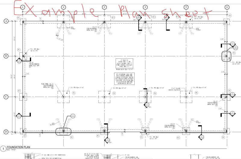
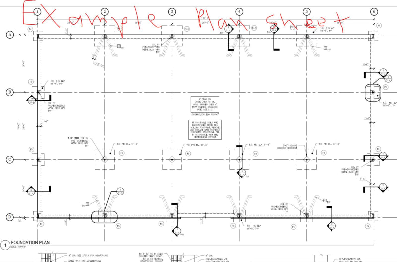
Question: Are hairpins at the corner columns necessary? I ask because I have come across plans that do not show them in the slab (see image below).

corner_hairpin_sqm2gx.jpg


If they are necessary, what is the best practice to detail them on construction documents?
 
What would be the reason for not having hairpins at the corner columns? What would be the reason for having hairpins at the corner columns?

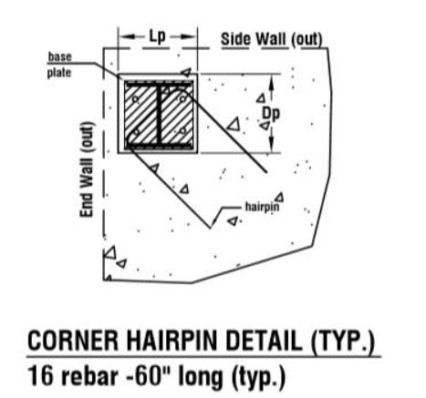
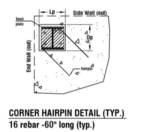
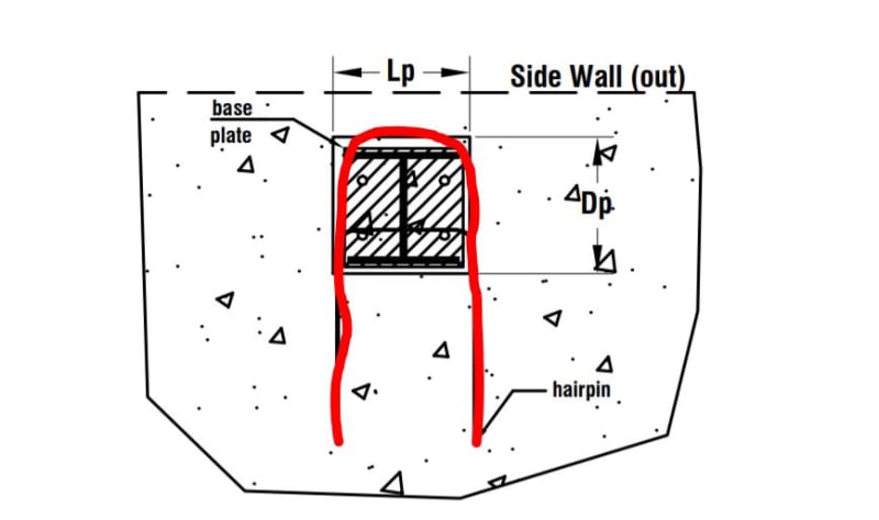
Would this detail work (see image below)?
corner_hairpin_2_zcxx7w.jpg
 
Often the end walls have intermittent wind posts that support the beams such that large amounts of corner column base thrust are not developed. Additionally, if appreciable base thrusts do develop, it is often possible to transfer those loads into the perimeter downturn / grade beam.
 
KootK said:
Often the end walls have intermittent wind posts that support the beams such that large amounts of corner column base thrust are not developed. Additionally, if appreciable base thrusts do develop, it is often possible to transfer those loads into the perimeter downturn / grade beam.

Okay, thank you for mentioning the wind posts. My pre-engineered canopy will be open all around, so I do not foresee there being any wind posts attached to the canopy.

So, it seems that hairpins at the corner columns would be advantages to use in my specific situation.

Would you happen to know the best practice for detailing the hairpins at corner columns?

Would the detail I show in the previous post be best practice?
 
As I mentioned in my last post, why not resist the thrust with bars in the downturn / grade beam? If you go with slab hairpins, I'd go with a pair of them oriented orthogonally and enclosing all of the anchor bolts.
 
In the example plan above, it seems there is grade beam along each edge, which is capable of acting as tension tie, so the corner column is well confined, and the lateral movement is prevented by the reinforcement in the grade beams. for unreinforced SOG, you do need to check concrete strength around the column, and provide hairpin as shown on the sketch.

 
retired13 said:
In the example plan above, it seems there is grade beam along each edge, which is capable of acting as tension tie, so the corner column is well confined, and the lateral movement is prevented by the reinforcement in the grade beams. for unreinforced SOG, you do need to check concrete strength around the column, and provide hairpin as shown on the sketch.

Sorry, which sketch are you referring to?

Is it the sketch in Image 1

corner_hairpin_2_wihzmq.jpg


Or the hairpins shown in this plan view, Image 2

corner_hairpin_l7eos5.jpg
 
The detail for the corner column.
 
KootK said:
As I mentioned in my last post, why not resist the thrust with bars in the downturn / grade beam? If you go with slab hairpins, I'd go with a pair of them oriented orthogonally and enclosing all of the anchor bolts.

retired13 said:
The detail for the corner column.


Thank you both for the inputs.

Would this detail, in the image below, be structurally acceptable as well? I am thinking this because I believe that this is the direction the force would travel in to the hairpin.

corner_hairpin_3_ieigwa.jpg
 
Status
Not open for further replies.

Part and Inventory Search

Sponsor