Continue to Site

Eng-Tips is the largest engineering community on the Internet

Intelligent Work Forums for Engineering Professionals

  • Congratulations KootK on being selected by the Eng-Tips community for having the most helpful posts in the forums last week. Way to Go!

Pre-Engineered Metal Building with baseplates below finished floor

Status
Not open for further replies.

Ben29

Structural
Aug 7, 2014
316
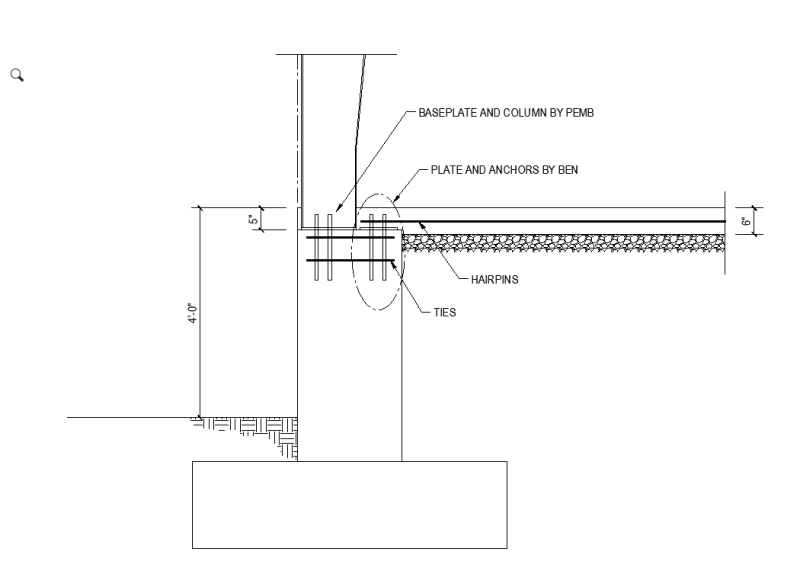
I am designing the foundations for a PEMB where the bottom of baseplate is 5" below the finished concrete floor. Normally I use the hairpin method to transfer the horizontal forces into the slab on grade. But I cannot do that now that the baseplate is lower than the top of slab. What is the next best option? Moment-resisting foundations?

Has anyone ever seen this before where the bottom of base plate is below the slab elevation?
 
Replies continue below

Recommended for you

You might weld rebar couplers onto the column and thread dowels into those that project into the slab. I do preferer moment resisting footings but those can be a tough sell.

 
Can you post some basic details so we can see the arrangement? For instance, is the column tight to the edge of the slab, or will you have bypass girts and another 8" of slab outside of the column flange? If you have room, you could still put in hairpins around the whole column to drag the lateral thrust back into the slab. If you don't, then I'd put a tension tie below the slab. It will be continuous bars that go from one set of anchors on one side of the building to the anchors on the other and will be encased in concrete.

Of course, hairpins are only useful for reinforcing the anchors, not really resisting thrust unless you have some funky angled development with the slab bars. So I may be misunderstanding your concern.

 
Are you sure you can't use hairpins? Get the load out of the column into the slab before it gets to the anchors.
 
phamENG said:
...not really resisting thrust unless you have some funky angled development with the slab bars.

For better or worse, it has been my experience that hairpins are typically used in exactly that way. The Butler manual of antiquity said so and thus it has been ever since.
 
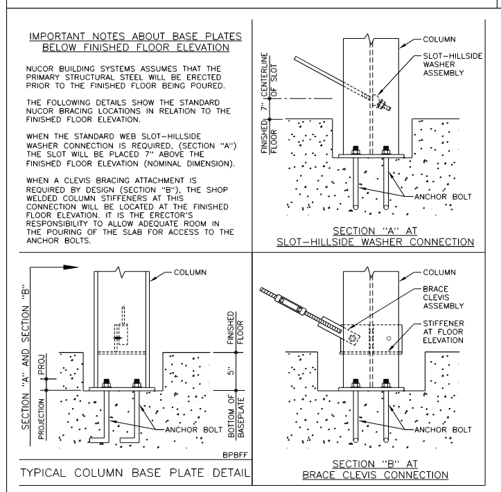
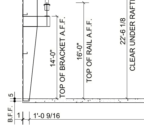
Here are some details from the PEMB drawings...
nucor1_fibwud.png

nucor2_cgsh4r.png
 
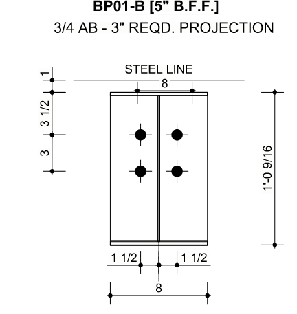
I think the edge of slab wants to be at the steel line (which is 1" off of the outside face of baseplate).


nucor3_cfih7h.png
 
I make it a point to not modify any piece of the PEMB elements, so welding a rebar coupler to the column is a no-go for me.
 
KootK - I know. And through a combine miracle of lower than design loading and latent concrete tension capacity, these things don't fall down all over the place. Though they do seem to fail more often than other steel structures - especially during construction. When I use hairpins for this purpose (often because a contractor convinces the owner that my discreet tension tie is unnecessary and my emailed copies of building failures for inadequate tension resistance in the slab go unread), I check development with the slab reinforcing and usually define a reinforced region in the slab along the frame line to resolve the tension in the steel alone.

I got really excited when I was sent to check out a building to design a build out. It was a PEMB and the original EOR had designed it with hairpins in the slab. Well the developer decided they wanted to leave the slab out so tenants could put in their own under slab plumbing, etc. So I walked in and here was this big PEMB with no slab and hairpins sticking out of a stem wall at the columns and bent vertical so they wouldn't get it the way. Yikes.

Back to the matter at hand...I'd do this:

Screenshot_2022-03-25_125616_dhole0.png
 
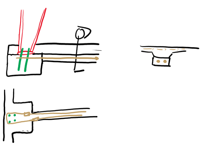
Would something like this work?

nucor4_y93nvg.png
 
If you design it as a non-contact lap splice you might be able to, but you'd be better off with a few more yards of concrete (once you get into the strut and tie discussion with KootK on how a non-contact lap splice works you'll understand why). But considering there's a cold joint in there it's unlikely.

Any reason you don't want to put a dedicated tension member beneath the slab? If it's an aversion to doing something "different" you can forget about it. That ship sailed when you wound up with PEMB base plates below TOS. It's not new, but it isn't SOP. So that means your solution probably can't be SOP either.
 
pharmENG - thank you so much for your input. I called the PEMB designer and asked them why they buried the baseplate. They told me that the client wanted a smooth slab on grade and this was the only reason. Well, when the client hears that this is going to cost them $$$$$$, perhaps they won't mind seeing those anchor bolts afterall.
 
Ben - you have a 4' retaining wall, so you have a continuous footing that's either capable of resisting the moment or is tied into the slab. With some careful detailing you may be able to use that to your advantage. Increase the slab/wall connection capacity on either side of your column for a reasonable distance and detail a load path for the load to go from the base of the column, into the wall, and back up into the slab and across to the opposing load on the other side. Or increase the footing width at the pedestal if you have it designed as an unrestrained wall with a floating slab.
 
I'm guessing it has to do with familiarity. It's also a niche area that gets limited exposure to the outside world. I remember talking to a product engineer a few years ago about something or another...they kept quoting design parameters that were way off from what the code required. I finally asked him what version he was using...ASCE 7-98. This was in 2015 or so. He was shocked to hear that we didn't actually use it anymore in practice. Not sure if I was the first to turn over his rock or if I was the first one to point out that he was, in fact, living under a rock.

Besides, it rarely matters. Most PEMB jobs I work on I have to specify the emedment anyway, so the PEMB manufacturer doesn't always supply the anchors - that's part of the foundation package. I just have to make sure the bolt size matches the holes in the base plates.
 
I agree with phamENG, when I have done this a few times in the past I have done a tie beam across the building, it didn't add that much concrete overall on these projects, however these were 60+ feet tall and 120+ feet wide sports centers, so the amount of concrete just for gravity alone was crazy, not to mention that they had cantilever CMU walls around the perimeter and choose grade beams spanning between caissons to support said walls. In that case, it was for a university so cost wasn't the driving factor from what I understood.

@AskTooMuch - In my experience, they design the diameter and grade of bolt only, you are to determine if it's heavy hex, J, etc.. as that comes into play more with concrete breakout which is on the EOR to design and figure out.
 
One thing to note, I'm not sure of your forces you are using hairpins for, but in my experience I have typically limited hairpins to around 10 to 15 kips force as after that you may not have enough weight/friction resistance without lapping to another hairpin/column line which also has it's own forces needing resistnace. Typically for larger buildings it ends up as tie beams.
 
Can you fill the pocket with non-shrink?

Rather than think climate change and the corona virus as science, think of it as the wrath of God. Feel any better?

-Dik
 
Hairpins have to be able to take the thrust if they are able to resist anchor breakout, the forces are one and the same. Thrust forces don't stop at the end of the hairpin, so if you think it's only for anchor breakout all you're doing is moving the breakout cone down the line.

I would just do what phameng recommends, or even just leave the thread bar in ground and not concrete, depending on ground conditions.
 
I have only designed 2 PEMB's before, so I am definitely still learning about how these work. I used tie beams below the slab on grade. I was concerned about the Owner wanting to cut the slab on grade or it needing repairs in the future. I was unsure about their knowledge of the importance of those reinforcing bars near the columns and thought the chances of them being cut were higher than I was willing to accept.
Also, from what I remember, the pier sizes and pier reinforcing are determine using the struct and tie method. I remember not being able to get the calculation to work with the anchor bolt spacing supplied by the PEMB engineer so I specified anchor bolt placement on my drawing.
 
Status
Not open for further replies.

Part and Inventory Search

Sponsor