Eng-Tips is the largest engineering community on the Internet

Intelligent Work Forums for Engineering Professionals

Pre-Engineered Metal Building with baseplates below finished floor

Status
Not open for further replies.

Ben29

Structural
Aug 7, 2014
313
0
0
US
I am designing the foundations for a PEMB where the bottom of baseplate is 5" below the finished concrete floor. Normally I use the hairpin method to transfer the horizontal forces into the slab on grade. But I cannot do that now that the baseplate is lower than the top of slab. What is the next best option? Moment-resisting foundations?

Has anyone ever seen this before where the bottom of base plate is below the slab elevation?
 
Replies continue below

Recommended for you

Off topic but I think helpful piece of information: the PEMB engineer will not design anything that extends into the your concrete. So the fasteners that attach the bottom girt to the concrete is on you. Same for fasteners that attach the door/window jambs to the concrete.
 
Most of the times when I've pitched discrete ties, I've been coerced into just using the slab on grade. Clearly I need to toughen up and improve my powers of persuasion.

phamEng said:
Once you get into the strut and tie discussion with KootK on how a non-contact lap splice works you'll understand why

In a similar vein, I wonder if a partial cross tie might be an attractive in some situations. I could get behind that. The far end wants to rotate down into the earth anyhow.

c01_szvwfy.png
 
KootK said:
Clearly I need to toughen up and improve my powers of persuasion.

If you're proposing to start a thread convincing a bunch of engineers that mass doesn't exist, I really hope you don't need that much work in this area.

I like your partial cross tie from a technical perspective, but I'm not sure I'd want to be the salesman.

Pros:
Eliminates the tie beam below the slab which many see as different and, therefore, frightening.
Reduces material usage for large buildings

Cons:
It's still different and, therefore, still frightening.
The design is slightly more complicated
The implementation involves more pieces that have to be fabricated
Removes some resiliency as compared to the tie beam - as Gopher mentioned somebody is likely to cut a trench to put a toilet in there eventually. The effect is worse for larger buildings where those tension loads get real.
 
Gopher13 said:
I remember not being able to get the calculation to work with the anchor bolt spacing supplied by the PEMB engineer so I specified anchor bolt placement on my drawing.

I hope you communicated the issue to the PEMB supplier first.

I could imagine this going down...the PEMB supplier provides a layout, I provide a different layout, the GC never checks (because how many GCs actually take proactive steps to coordinate anything?), the foundation contractor installs anchors per my layout, the PEMB shows up on a truck and...doesn't fit. Womp womp. Who do you think is going to get fried for this one? (I can assure you it isn't the PEMB manufacturer.)
 
phamENG: my situation is a bit unique. I am a full time employee of the owner. PEMB shop drawings are sent to me. I comment on their anchor bolt placement not matching mine and mark "revise and resubmit." But you are right, their PEMB shop drawing has never matched my layout on the first try.
 
Too often the project delivery for these gets bungled and I'm not involved until the PEMB is already in the production pipeline. I know that's the case for others, so I just wanted to speak up before an EIT out there on Google found this thread and thought that was all they needed to do.

Sounds like you have a good handle on keeping them in line.
 
phamENG,

Had that happen to the company I work for. We had the anchors drawn right in the overall plan view, but the pier details (where we show the anchor details)still showed the layout from the prelim drawings (which, of course, changed). We missed that and got to eat the whole fix.

I'm still salty that the GC asked for a CAD file of the overall plan WITH the anchors drawn on it (which were located correctly), but then didn't use it for locating the anchors. Alas.
 
phamENG said:
If you're proposing to start a thread convincing a bunch of engineers that mass doesn't exist, I really hope you don't need that much work in this area.

Ha! I can persuade engineers just fine. It everybody else where I struggle.

phamENG said:
The design is slightly more complicated

Pish-posh, this shouldn't be any harder than anything else if those other things are being done properly.

phamENG said:
The implementation involves more pieces that have to be fabricated

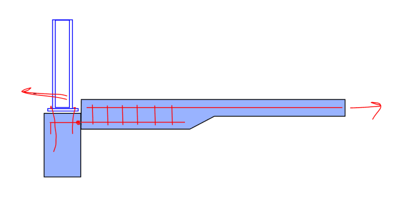
Pish-posh. Just a little rebar that was likely to be there in the form of hairpins initially anyhow. I'd even be willing to omit the ties if the bar offset was <= 6"

phamENG said:
Removes some resiliency as compared to the tie beam - as Gopher mentioned somebody is likely to cut a trench to put a toilet in there eventually.

That kind of depends on how you look at it. If you put all of your eggs in one basket with a tie beam, someone might come along and chop that anyhow if they really need a toilet. If we used my partial ties to get the load out into the SOG convincingly to begin with, then there would likely be plenty of possible load paths for the tie force in a 6" slab to go around a toilet. You know, unless somebody comes and installs a big, building wide trench perpendicular to the ties. There's only so much hand holding one can do of course.

One thing that I like about my partial tie stirrups is that, hopefully, those would trigger some thinking when encountered during a renovation.

Naturally, a tie that is integral will the SOG can be the best of both worlds potentially. When I've done discrete ties, they've actually been separate from the SOG so as not to mess with shrinkage cracking, joint layouts etc.

 
It really is a shame the rebar couplers are out for warranty/liability reason. It would have been a gloriously direct load path otherwise. And you'd have a tough time convincing me that it would do any real harm to the PEMB columns.

c01_ktbjjr.png
 
With regard to tie beams of all sorts, I believe that ACI has some special requirements:

1) No lap spicing. It's gotta be mechanical, weld, strut and tie, etc.

2) More onerous crack control. And this is good as it keeps us from designing the ties to As x fy and having them stretch out like big rubber bands.

#1 implies that my solution would have to include the ties however.
 
I called the PEMB designer and asked him what was up with the baseplate being -5" below top of slab. He said that the owner wanted to have a smooth slab. I asked him if raising the baseplate to the top of slab would change anything with his design. He said no and condescendingly explained to me why this wouldn't change his design. But I digress...

My next call is to the architect. Mr. Architect, can you please explain to your client that lowering the baseplate is going to cost him more money due to x, y, z.

30 minutes later, the client makes the decision to move the baseplate to the top of slab.

Welcome back to your regularly scheduled program.
 
Status
Not open for further replies.
Back
Top