Continue to Site

Eng-Tips is the largest engineering community on the Internet

Intelligent Work Forums for Engineering Professionals

  • Congratulations SSS148 on being selected by the Eng-Tips community for having the most helpful posts in the forums last week. Way to Go!

Press Tie Rod Nut as Projectile

Status
Not open for further replies.

Pete_K

Mechanical
Sep 23, 2015
50
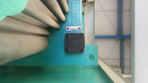
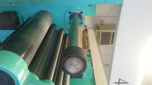
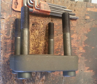
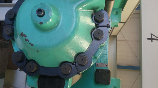
A customer of ours asked us to look into something for them. They have a number of large presses. The presses have large bases at either end, tie rods connecting the bases, and a large hydraulic cylinder which creates a rather large separating force.

They infrequently experience failures of the tie rods, where after the failure the tie rod fragment along with the nut shoot away from the base with some decent speed. They welded in restraints meant to stop the fragment/nut, but are now questioning whether these restraints are satisfactory. We had previously offered to help them review the material, threads, and pre-tensioning, but as of right now they're only interested in making sure the guards are OK.

So, my issue is in determining what loading I use to evaluate the guards. The tie rod, when loaded via actuation of the hydraulic cylinder, stores an amount of elastic, or spring, energy. What happens when the break occurs? Does all of that (minus minor losses) become kinetic energy of the fragment/nut? Or is some of that energy shared with the remaining length of tie rod and its nut?

Or rather is the accel of the fragment/nut due to stored elastic energy of the compression of the base and nut?

Is the stored energy of the tie rod equal to the stored energy found in the bases? Looking thru some bolted joint stiffness calcs and finding that energy, I don't believe this to be so, but the more I think about this, the more complex it is seeming to me. And the more complex it seems, the more I think I should just keep it simple and choose a very conservative approach.

I've been looking thru a lot of texts and trying to research this, but just can't find anything that answers my questions, though I have found others who have posted similar questions. I've included a really rough sketch to hopefully convey the basic form of the press.

I appreciate any and all comments, suggestions, etc. that anyone can offer. Thanks.
 
 http://files.engineering.com/getfile.aspx?folder=d096e008-81a9-4ef1-99b6-1a481f2b3ce7&file=Press_Sketch.pdf
Replies continue below

Recommended for you

If the bases are much stiffer and much heavier than the tie rods, I would assume that all of the propulsion comes from elastic energy in the tie rod. I would assume that most of the elastic energy stored in the base assembly is used in moving the base assembly, not in moving the tie rod.

Side note: One of the known hazards of towing/winching is that cables or chains under high tension can be very hazardous when they break. Once upon a time, I was working for a dump truck company. They had a heavy bobtail truck stuck, were trying to get it out with a track loader, and the chain broke at the track loader. The hook from that chain went through the windshield of the truck and broke the rear window.
 
Youtube search for tractor/truck wheel inflation cages (tyre cages).
I wouldn't be concerned for exact calcs but I'd heavily overdimension the cage.

Probably not what you wanted to hear but here safety is a concern, a FoS of 10 (or more) would still be acceptable according to me. Probably not worth doing the calcs for.

 
Hi BQ09

Have you any pictures of the failed tie rod, nut etc?
Reading your post it suggests the rod is failing and the threaded part of the rod is still engaged inside the nut when it flys across the workshop, if that is the case I would look at possible fatigue in the tie rod assuming the cylinder is loaded cyclingly. If you can get hold of a tie rod look at the fracture face it might show classic marks of fatigue.

“Do not worry about your problems with mathematics, I assure you mine are far greater.” Albert Einstein
 
Agreed, it sounds likely the rod/nut interface is probably experiencing low cycle fatigue.
Pictures of the failed cages, and better yet, some of the actual ailed cages are required, too, if you'll be evaluating the guards, as directed by your customer.

Does the nut escape thru/around the cage on the first rod breakage, or only after multiple strikes ?
I'm thinking some amount of controlled deformation is almost mandatory if the nut/stub is to be contained. If that deformation is provided by the cage, and the deformation is severe, then the cage only has so many life cycles, which users might not recognize.

Perhaps some replaceable, sacrificial deformable element would make it easier to "reload" the catcher system to full capacity.

Maybe could even turn into a replacement parts business for someone.
 
Looking at your diagram there doesn't appear to be much scope for the elastic energy in the tie rod to be transferred to kinetic energy in the nut. Most of it goes to the rod itself - complete with the other nut.

je suis charlie
 
Here are some photos of a 200t clamp injection moulding machine tie bar arrangement. As it happens, we have one out to get a large tool in.

The majority of tie bar breakages are due to incorrect/uneven tensioning. In 25 years in this business I have never seen one break, but have heard of instances.

On the pics below, the black collar on the tie bar end has been marked by the manufacturer to get the same tension as designed and as built. (The tie bar has to be heated to enable getting the correct pre-tension on re-assembly)

Note the pics have rotated 90 clockwise somehow - after spending half hour on Photoshop getting them correct orientation!

Tie bar clamp in situ:
Tie_bar_clamp_in_situ_dpu0km.jpg


Tie bar with clamp off and extracted:
Tie_bar_out_liuxim.jpg


Tie bar clamp and M20 bolts:
Tie_bar_clamp_off_uthdfa.jpg


Safety restraint around clamp cylinder studs:
Clamp_Cyl_safety_zvfikr.jpg


www.tynevalleyplastics.co.uk

Politicians like to panic, they need activity. It is their substitute for achievement.
 
Thanks everyone for all the responses, it's much appreciated.

Regarding why the tie rods themselves fail, I'm fairly certain it's fatigue since I'm sure they don't properly pre-tension the tie rods. They say they get 10 years out of them, so they're not very interested in doing the work to extend the life.

I don't have any info on how their existing guards may have failed...I was told that they had a failure at another facility. I've requested pics of this, or some description of the failure, but have not received anything as of yet. I'm gonna make a point that I can't continue on without that information.

I would expect that after a strike the guards may need to be replaced...like a bicycle helmet, once it's employed to do it's job, it gets thrown away.

gruntguru said:
Looking at your diagram there doesn't appear to be much scope for the elastic energy in the tie rod to be transferred to kinetic energy in the nut. Most of it goes to the rod itself - complete with the other nut.

Yeah, this is the part of this that has me confused...I'm trying to figure out the dynamics of how much energy goes into propelling the fragment/nut versus the share of it that would go with the rest of the tie rod, as it has a huge impact on this.

Thanks again, I'm always impressed by the helpfulness of this community.
 
It won't be easy to establish it IMO, but its all about the bases and the Separating Force as per your diagram.

The force exerted by the nut is resisted by the base which must then either compress or move / bend, ever so much. given that the movement is likely to be low, but the bending moment very high, this is what gives the nut the force / velocity, IMO.

The energy is in the base, not the rod, but is equal to the energy in the rod (force x distance).

Think of it this way, if the base on the LHS was effectively solid / very big/stiff, but the base on the Right much more flexible, as you tighten the nut the base on the RHS moves, storing energy caused by force x movement. As the nut breaks, the base returns to its lowest form of energy, imparting some/most of said energy to the nut.


Remember - More details = better answers
Also: If you get a response it's polite to respond to it.
 
If the two bases are equal, then the energy in the rod is halved between each end , but as the mass of the rod plus bolt is a lot higher, then the velocity of the rod is much lower. Don't know if it was deliberate, but you show one base bigger / stiffer than the other

Remember - More details = better answers
Also: If you get a response it's polite to respond to it.
 
Thanks.

What I run into with the energy balance is that essentially the tie rod is a (relatively) soft spring in tension, and the bases are very stiff springs in compression. I have not quantified it, but the stiffness of the bases has to be a decent multiple of the stiffness of the tie rod (analogous to a typical bolted joint where the clamped materials have a much higher stiffness than the bolt).

Spring energy then being E = (1/2)*stiffness*(delta^2), I don't get the two to equal each other. The attached pic is a really simplified example of this. Perhaps the conservative approach is to use half the stored tie rod energy.
 
 http://files.engineering.com/getfile.aspx?folder=a89af6eb-dc10-4d2d-90d6-8faae7dab21b&file=spring_energy_example.JPG
Ignoring for a minute whether or not the physics of the problem allow it, what it the velocity/energy/mass of the projectile if you assume all of the stored spring energy goes into a given piece? Perhaps it's not that "bad" even in the extreme case. Then again, maybe it is bad, and you'd be trying to stop a theoretical cannon ball.

 
In that scenario where all the spring energy of the tie rod goes into the fragment, it would be going 33 feet / second. The fragment weighs 350#. While 33 feet/s doesn't sound terrible, it ends up being a decent amount of kinetic energy.
 
150kg!! That's some "nut"

Do you have a photo?

Remember - More details = better answers
Also: If you get a response it's polite to respond to it.
 
Wow. That's much heavier and slower than I had envisioned. I pictured a 15 or 20 pound nut flying out much faster. PING!

It is a decent amount of energy though, about as much as the muzzle energy of the largest shoulder-fired rifles. It would also be like hitting a 350 pound animal with your car, going 22.5 mph. That would certainly do significant damage...and animals are much softer and less dense than press parts. Of course, such comparisons are fun, but not necessarily directly applicable.

I'd guess that the energy is manageable without a highly specialized solution. In other words, not like the examples of big tires or flywheels exploding. For testing, you can achieve 33 fps by dropping the "projectile" from a forklift or something.
 
Holy moses. That's some "nut"

My concern over that as shown is whether the nut could squirm around it or over it if the bar isn't dead centre, plus the fracture might make it fly off slightly off centre.

Two of those slightly apart would work, but for energy / force you need to use the stored energy / force in the bar I think which just instantly transfers to the nut.

Remember - More details = better answers
Also: If you get a response it's polite to respond to it.
 
Well, there sure isn't a whole lot of extra space in front of that nut. See the attached depiction for a device that would fit into the same space as the existing guards.

I believe the wire rope element might absorb the blow softly if it were sized right. It probably wouldn't be too expensive, either. Most any shop could make it, except for the swaging operation.

Caveat: It's a completely untested idea that I pulled out of the air...on a Friday morning...while eating a sandwich.

Edited to add: It might be less of a hassle to use a bundle of smaller wire ropes, like 1" diameter, independently swaged. Weld the bundle of swaged fittings (not the rope itself) together. In the case of the giant wire rope, swaging might not be needed. I'd imagine that the wire rope could simply be inserted into the tubing a generous amount and held in by some less sophisticated method...like through bolts, or welding (away from where the tubing would flex).
 
 http://files.engineering.com/getfile.aspx?folder=ae7329ee-fe78-4237-bafa-5fc100064d82&file=nut_stopper.pdf
Status
Not open for further replies.

Part and Inventory Search

Sponsor