Continue to Site

Eng-Tips is the largest engineering community on the Internet

Intelligent Work Forums for Engineering Professionals

  • Congratulations KootK on being selected by the Eng-Tips community for having the most helpful posts in the forums last week. Way to Go!

Press-together crank vs a billet crank 2

Status
Not open for further replies.

Billzilla

Aerospace
Jun 14, 2017
9
I'm designing a V8 engine, mainly for the challenge, and I've been trying to decide on either a conventional billet crankshaft or a press-together one. I have no doubts that the plain billet crank would work just fine, but I don't want to discount the advantages of a press-together type as it makes the machining to get the rotation mass down a bit easier. I thought that with the very accurate tolerances available with good EDM gear, I could make the connecting surfaces have shapes that aren't the typical round profile that's locked together with a spot of weld, but, for example, have a round section that has two parallel sides on it. That would lock the various parts together quite accurately & firmly.
I was also wondering about the strength of such a PTG crank, as it wouldn't have the stress areas around the journals like a regular crank would.
So, any thoughts or suggestions please?

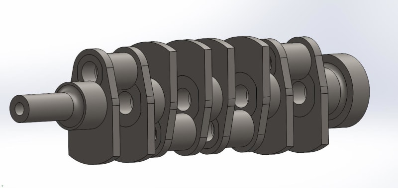
Note that I haven't calculated the counterweight masses & sizes, so the pictured cranks are just as an example.
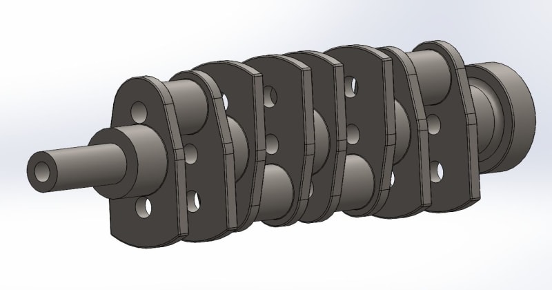
Billet_crank_zupplr.jpg


PTG_crank_lbfho1.jpg
 
Replies continue below

Recommended for you

Built-up crankshafts are common in slow speed diesels where machines aren't large enough to turn an entire crankshaft. Some manufacturers have experimented with welded assemblies because they feel there are disadvantages to the built-up design.

For smaller engines, the built-up design is typically used for engines with roller bearings which makes using split connecting rods a challenge.

It might be possible to make a built-up v8 crank but the labor of assembly and getting each segment timed correctly would be exorbitantly expensive.

I also feel that the built-up crank requires extra mass around the connections to provide sufficient grip from the press fits. This may add weight to the assembly which may be detrimental.
 
You should have another read of what I wrote. I wrote that instead of the usual round mating areas, by using very accurate EDM gear I could make them fit very neatly & accurately. No need to align anything because they only go together one way.
I do like the idea of using roller bearings as it'd reduce the amount of oil flow & pressure a fair bit.
 
Dirt bikes use built up cranks. I know many shops refused to rebuild Honda 2-stroke cranks because they had sheet metal shoes on them so they couldn't be straightened after assembly. They had to be built straight which required special fixtures. Apparently, having cylindrical bores and a pin wasn't enough to ensure proper alignment.

Not trying to be a negative Nancy here, just thinking about existing examples.

Roller bearing cranks have been done before. They have a lot of mass and a finite fatigue life. They are only preferred for challenging applications such as 2-stroke engines without oil sumps and dirt bikes which may have interrupted oil flow. Outside of those poor lubrication cases, the journal bearing is superior.
 
I'm not sure how you're not getting this - The areas where they join wouldn't be round the entire way around, they'd have a couple of parallel sides to the parts can only go together one way and with perfect accuracy.
You can't see it very clearly in the screen captures above, but I have a way of taking quite a lot of weight out of the crank.
 
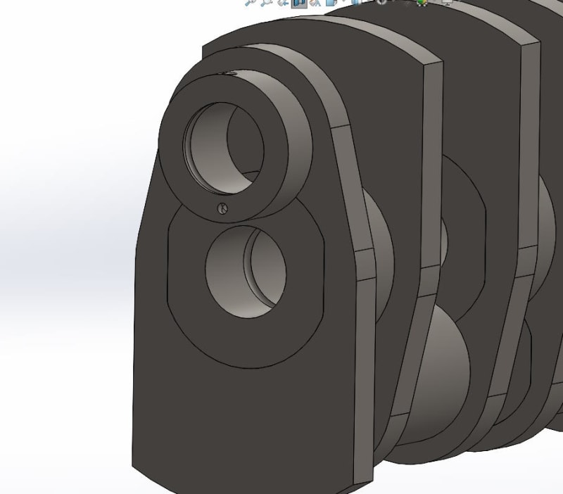
Here's a view with a little bit of the crank cut off so you can see the main journal a bit better. Note the parallel sides on the pin. It can only go in one way (unless you fit it 180º out!) and so quite accurate.

fghjuk_orqcf5.jpg
 
That won't result in a uniform press fit, but if you are going for EDM you can get a much closer approximation using a version of the Torx form to avoid a stress concentration in the corner and the continuously varying force along the flats.
 
Interesting idea. Honestly, my opinion depends on your goal. If this came across my desk at work I would say that it needlessly complicates production and results in a weaker crank. As a hobby challenge tho, sure, it could work and run. I have quite a few friends among the model-engineering hobby crowd and this is pretty normal compared to many of their ideas.
 
The engine it's intended for is a three litre 10,500 rpm V8. 83mm bore 59mm stroke.
 
There is no need to design one as plenty are available. The push is for electrical motive. Its an exercise of reinventing the wheel.
So this must be a personal hobby deal?
 
Billzilla said:
You can't see it very clearly in the screen captures above, but I have a way of taking quite a lot of weight out of the crank.

Something (well... your posts) tell me you haven't done any stress evaluation yet, or put any thought into that aspect of your design.

Your interfaces must be press fit. It's not optional. If they aren't, the clearance of even the finest slip fit will result in relative movement between parts; crankshaft loads are reversing loads. Any relative movement at all will result in catastrophic part failures, and they will happen quickly. At 10,000 RPM, any part of an engine reaches millions of load cycles in a matter of hours.

If you have to have press fits (which you do) that also means your mating parts, both male and female, need enough material to handle their service loads plus whatever additional load results from the press fits at assembly. These loads never go away - after all they need to be there to keep your parts together.

This means that building a crank that's pressed together and as light as one that is made from billet is not possible. Note above the list of applications that use press fit cranks; none of them use a press fit crank because its stronger or lighter. They use it because some other condition makes a single piece crank impossible.

In short, your press fit crank assembly is going to be more expensive, heavier, and less strong than a billet crank of the same material.

If your goal is maximum performance, minimum cost, or both, just use billet. The only reason to do it the way you're describing would be for its own sake. If that's what your goal is, well, fine. But it won't be 'better' in any conceivable way.
 
"Something (well... your posts) tell me you haven't done any stress evaluation yet, or put any thought into that aspect of your design."

Yes, I did mention that.


"Your interfaces must be press fit. It's not optional."

Of course they are. I'd have to sit one part in a bath of liquid nitrogen and heat the other part with an oxy torch. Then quickly press them together.
And yes I could get a billet crank pretty light, but not as light as the way I'd do the pressed crank. Got a few tricks that would take a lot of weight out of it.
 
Billzilla said:
but not as light as the way I'd do the pressed crank

I don't think you understood my earlier post. But you seemed to come here for validation of what you've already decided, so good luck I guess. Hopefully you get out of the ideation stage and actually build something.
 
No I did get it, I'm just trying to discuss the alternative to the typical method of connecting the various parts of a press-together crank, by having high precision mounting surfaces made by EDM gear, with the intent that it both perfectly aligns the two parts and also locks them together to eliminate the possibility of the two losing alignment.
The loss of alignment seems to be the main problem with PT cranks, and for the reasons mentioned previously.

I do consider your mention of the stresses caused by the interference fit between the various parts, but the degree of interference could be reduced because of the interlocking shape of the two parts. Further up a chap mentioned that a Torx-type joint between the two parts would probably be better and I think he's correct. But I don't think it'd be needed all the way around, just three or four bumps/dips to lock the alignment between them. I can draw up a diagram to make that clearer if you like.

In any case I'm certainly not determined to go down the PT crank path, it's just something I want to have a good look at before either using it or not. The reduced oil requirement for a PT crank with roller bearings is very tempting. I know a plain old billet crank would work just fine, but I want to do the best job I can, not one that's merely okay. ;)

Anyway all good info, chaps, keep it coming please.
 
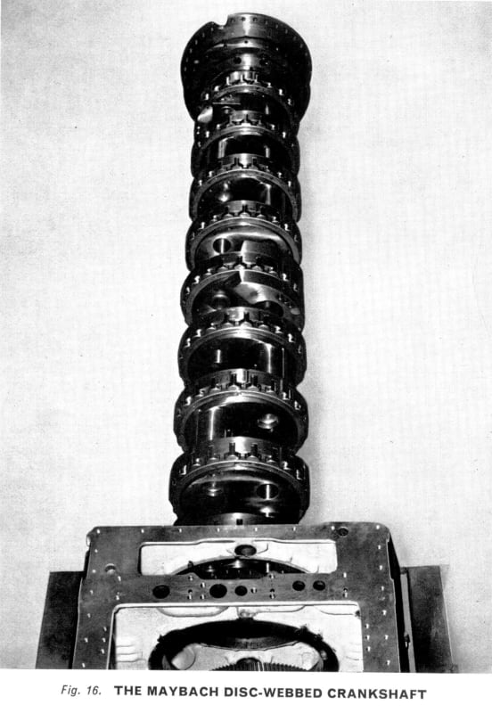
For a stronger, easier to machine, and much more compact crankshaft, consider the disc-web crankshaft where the webs are the main bearings. There have been both roller bearing versions and plain bearing versions of this style crank in the past. In the case of the plain bearing version shown here, the crank was a hollow iron casting. This style crank requires a tunnel crankcase.

Maybach_Roller_Crank_zujehi.jpg
[URL unfurl="true"]https://res.cloudinary.com/engineering-com/image/upload/v1681251144/tips/Tatra_Disc-Web_Crank_rxtxe6.bmp[/url][URL unfurl="true"]https://res.cloudinary.com/engineering-com/image/upload/v1681251171/tips/Gleniffer_DHV8_Crank_wpcwor.tiff[/url]
 
Billet all the way...

A press fit together crank is a nightmare to build up - At least I hate doing it... Something thats wire EDM'd, would be even moreso I'm guessing.

Keep in mind too oil way drillings in a built up crank...you're going to have to have a lot of grooves, 90deg drillings, and block off bungs in the big end journals.

Brian,
 
Status
Not open for further replies.

Part and Inventory Search

Sponsor