Continue to Site

Eng-Tips is the largest engineering community on the Internet

Intelligent Work Forums for Engineering Professionals

  • Congratulations waross on being selected by the Eng-Tips community for having the most helpful posts in the forums last week. Way to Go!

pressure in 2 tanks

Status
Not open for further replies.

a7med217

Mechanical
Mar 7, 2016
7
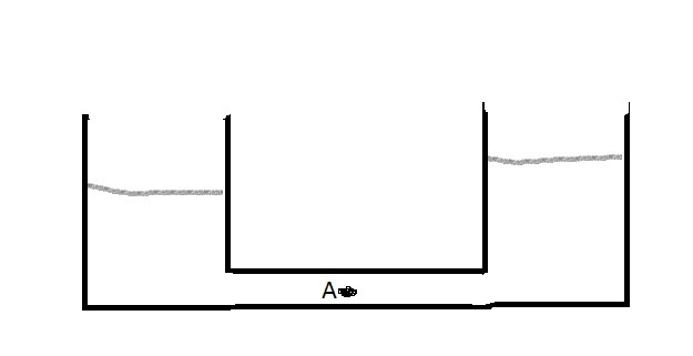
For this case, i have a distribution chamber which is continuously filled with water with head 7m to feed a clarifier with head 6m. my concern is the pressure for point A in this drawing
hdtwrt_htmmvj.jpg
.
if it will be the difference between the two levels or will be the total head in the distribution chamber.
note that this system isn't static.
 
Replies continue below

Recommended for you

Your drawing is impossible unless there is something in the connecting run that results in 1 m of head loss and a way for the clarifier to dump fluid and a way for the feed tank to accept new fluid (i.e., the dynamic head loss device in the horizontal run requires flow do generate a dP). Pressure on the in-feed side of dP would be 7 m of fluid (if that is point A) and pressure on the out-feed side of dP would be 6 m of fluid (if that is where point A is).

You should have been able to solve this by observation.

David Simpson, PE
MuleShoe Engineering

In questions of science, the authority of a thousand is not worth the humble reasoning of a single individual. Galileo Galilei, Italian Physicist
 
Here on earth water seeks its own level. As said, what you have drawn is not possible in a static condition.

Ted
 
The pressure will be midway between the two point if point A ia midway.

your drawing is somewhat simplified, but as you say it isn't static, so we have to take your figures on trust.

Your static pressure measurement may well be affected in this instance by velocity head if the velocity is fast enough - see things like this

You can often ignore it, but when you only have 1m head difference, it's not a lot.

Remember - More details = better answers
Also: If you get a response it's polite to respond to it.
 
LittleInch,
Really?????? What in the drawing would make you think that the two levels are possible? For a static condition, regardless of the hole size, the two levels have to be the same if there is a connection between the two tanks. For a dynamic condition, the difference will be the pressure drop between the two tanks. The pressure at point A will NEVER be the average of the two heights. It cannot be.

David Simpson, PE
MuleShoe Engineering

In questions of science, the authority of a thousand is not worth the humble reasoning of a single individual. Galileo Galilei, Italian Physicist
 
Isn't an orifice simply the extreme case? If you had a very small diameter pipe, such that the equalization time is long, then the condition is quasi-static, and the pressure drop will be developed across the entire length of the pipe, and the midpoint would be the average, would it not?

TTFN
I can do absolutely anything. I'm an expert!
faq731-376 forum1529
 
zdas04,

Because the OP said so, one side is a tank being "continuously filled with water" so it must be going somewhere and he or she says "note that this system isn't static". If it isn't static then it's dynamic or flowing. The drawing is lacking in important details such as showing the flow in and out or sizes or flow path, but we can only deal with what we get.

The wording is unfortunately underneath his picture, but too many don't seem to have read that bit?

If you assume the bit between them is a pipe and point A is half way along and the pipe is flat then why isn't the head / pressure halfway between the inlet head and the outlet head??


Remember - More details = better answers
Also: If you get a response it's polite to respond to it.
 
LittleInch,
If it were static the situation would be impossible. If it is dynamic then there is something (a valve, a filter, a strainer, an orifice, etc.) in the cross connect and if you take Point A on the downstream side of the dP then it reads the lower value. If you take it on the upstream side of the dP then it is the higher pressure.

Whatever is causing the dP would by its nature be non-steady-state and predicting the pressure within a varying element is pointless. Even if the dP were due to friction in a small pipe, dP due to friction is anything but linear along the pipe (closer to a fifth power function) so picking Point A in the exact center of that pipe would give you a number a lot closer to 6 m than 7 m.

David Simpson, PE
MuleShoe Engineering

In questions of science, the authority of a thousand is not worth the humble reasoning of a single individual. Galileo Galilei, Italian Physicist
 
"so picking Point A in the exact center of that pipe would give you a number a lot closer to 6 m than 7 m"

OK, so you're saying there can be a point that is the average of the pressures, then; it's just not in the middle?

TTFN
I can do absolutely anything. I'm an expert!
faq731-376 forum1529
 
zdas04,

I fully agree -if this was static it wouldn't work.

We don't know anything about the cross connect - it could be a pipe, a small channel or any data such as size, length etc, all we know is that there is a head difference of 1m between the two tanks. Now assuming this is liquid at a steady flow rate then the pressure drop per unit length is the same at the inlet as it is at the outlet if nothing changes ( diameter, surface roughness, shape etc). DP due to friction is constant for a liquid filled pipe.

"Whatever is causing the dP would by its nature be non-steady-state" - how do we know this - the OP has stated a single figure for the head difference, not "varies between X and Y" so it looks pretty steady state to me...

Remember - More details = better answers
Also: If you get a response it's polite to respond to it.
 
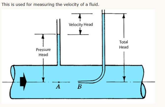
The total energy in the pipeline is the sum of the static, dynamic and hydrostatic pressures. The static pressure is the pressure as measured moving with the fluid that can be measured with a pressure gauge. The dynamic energy depends on the velocity head and will be relatively small. The hydrostatic pressures is the pressure due to the force of gravity

The velocity head can not be measured with a pressure gauge. You need a pitot tube to measure velocity head.

However, the hydrostatic pressure will depend on the elevation. If the pipeline is relatively level, the hydrostatic pressure will be constant. If there is significant elevation difference, then there will be differences in pressure due to the elevation. For those applications, the elevation head will have to be added to the static pressure.

For the application that you have proposed, the total energy will be midway between the tanks. The velocity should be relatively low for this application.

Document127_pddvwn_hamjab.jpg
 
IRStuff,
For gas (where I usually work, not that it has anything to do with this question), dP/length varies considerably from point to point down a line, and the lion's share of the total pressure drop happens early in the line. I was in a hurry this morning and improperly applied that same logic to liquid. For a gas it won't ever be in the middle. Liquids are generally assumed to have constant density so they will have constant dP/length down the entire line, and the average will occur somewhere very near the center.

LittleInch,
It has been my experience that things (all things in gas, everything but pipe in liquid) that cause a dP are imposing a market basket of forces on the flow and the pressure profile is always shifting within a device like a filter or a control valve. If it is just pipe (can't be a channel because there is non-trivial pressure on it and a channel would drain both tanks), then I suppose Point A would be the average of the two pressures.

David Simpson, PE
MuleShoe Engineering

In questions of science, the authority of a thousand is not worth the humble reasoning of a single individual. Galileo Galilei, Italian Physicist
 
Looks a lot like school work, and here its often finding the "trick", so as long as you add water to the right tank the level will be higher here than in the left chamber and the difference would be equal to the loss in the pipe+inlet/outlet between the two tanks. The fact that OP is concerned wrt the pressure at point A indicates homework since why would be be concerned with that? At the end of the day the pipe should be able to withstand the max pressure=max liquid level in the tallest tank.

Anyway what OP should do is assume that the loss is symmetrical (not entirely true since inlet loss is not the same as outlet loss. If you wish to compensate for this then you need to know the flowing velosity) and then just take half the difference in elevation (then pressure would be in m/in/feet water column) and if necessary convert this to pressure in the unit of his/hers preference

Best regards, Morten
 
additional thoughts,

flowing velocity should be fairly easy if you know the inlet rate and assume a quasi stationary problem (its SS but it wont go on forever) and the pipe diameter. A good approximation of inlet loss (from pipe to tank) is 1 velocity height and outlet (from tank to pipe) is 1/2 velocity height. Velocity height is V^2/2g and you can deduct that from the measured level difference - the remainder will be the loss in the pipe itself. The half that and add the "outlet" loss and convert (if required) to a pressure unit and you have you answer (assuming that A is a the middle of the pipe connection the two tanks.

Best regards, Morten
 
The "trick" here is keeping the velocity high enough so that solids do not settle out of the fluid. The elevation difference is really not that important in the bigger picture.
 
I will take "note that this system isn't static" to mean that there is some flow across point A. Therefore the difference in surface elevations will be the same as the head loss corresponding to the rate of flow across point A.

neglecting entry and exit losses

 
Status
Not open for further replies.

Part and Inventory Search

Sponsor