Continue to Site

Eng-Tips is the largest engineering community on the Internet

Intelligent Work Forums for Engineering Professionals

  • Congratulations Danlap on being selected by the Eng-Tips community for having the most helpful posts in the forums last week. Way to Go!

Pressure in vacuum line 1

Javier Sanchez

Mechanical
Feb 12, 2025
5
Dear all,

I need to design a system as depicted in the attached image, where I need to feed a fix flow of nitrogen to one membrane under partial vacuum conditions. The setup considers a nitrogen source from bottles and a vacuum pump at the end of the line. The idea is to use a pressure regulator and a flow meter, to feed nitrogen at 0.5 bar and 0.4 Nm3/h, and that the vacuum pump can decrease the pressure in the membranes further to 65 mbar(a). I would like to know how to calculate the pressure profile along the line, from the pressure regulotor to the pump, to know the pressure at which the membrane would be working. Do you know any suitable formula for such setup that can consider pressure losses and the curve of the pump? Thanks in advance!
 

Attachments

  • Setup scheme.jpg
    Setup scheme.jpg
    96.1 KB · Views: 30
Replies continue below

Recommended for you

Dear all,

I need to design a system as depicted in the attached image, where I need to feed a fix flow of nitrogen to one membrane under partial vacuum conditions. The setup considers a nitrogen source from bottles and a vacuum pump at the end of the line. The idea is to use a pressure regulator and a flow meter, to feed nitrogen at 0.5 bar and 0.4 Nm3/h, and that the vacuum pump can decrease the pressure in the membranes further to 65 mbar(a). I would like to know how to calculate the pressure profile along the line, from the pressure regulotor to the pump, to know the pressure at which the membrane would be working. Do you know any suitable formula for such setup that can consider pressure losses and the curve of the pump? Thanks in advance!
You’ll need to consider pressure drop due to friction losses in the tubing and the flow characteristics of your vacuum pump. The Darcy-Weisbach equation can help estimate pressure losses along the line, and you’ll also need the pump’s performance curve to determine the pressure at the membrane. Since you're working with a gas, compressible flow equations (like the isothermal or adiabatic flow equations) might be more accurate. If possible, checking experimentally with a manometer at different points along the line can also help validate your calculations!
 
For the pressures at which you are working, a well designed piping system will have essentially no pressure drop. All the pressure drop is going to be across the membrane. You should get the pressure vs flow characteristic for the membrane from the supplier and check that at the rated flow the actual area does give a pressure drop of less than 435 mbar.

Once you have the pressure drop across the membrane, and hopefully knowing the details of the piping, you will be able to use the isothermal compressible model to check that the calculated pressure profile matches the pressure drop available.
 
Your biggest issue is likely to be the line from the membrane to the vacuum pump as this is going to be about 10 times more actual volume than the gas line coming in. I'm not sure if pressure has an impact on friction factors or not, but for the same size pipe in and out the velocity and hence pressure drop will be a lot higher.

Short pipes though there is nothing in it so long as you're not approaching sonic velocity.
 
Hi,
Pay attention to the units, don't mix gauge pressure and absolute pressure, Use only Absolute pressure.
Regarding flow rate, need to be expressed in kg/s, not Normal m3/h.
Note: temperature profile is also needed to calculate the density of the N2 thus the mass flowrate.
Don't forget to define the Normal condition .
Good luck.
Pierre
 
The vacuum pump sizing basis is know as you already know the desired flow and suction pressure 65-67 mBara at 0.4 Nm3/hr. Therefore you can select a vacuum pump based on this flow and differential pressure on suction to whatever pressure is on discharge which I assume is atmospheric.

The piping is sized for about 60 ft/sec typically for gas for noise considerations. For properly sized piping (as Kumar stated) the pressure drop is negligible, therefore if you have a maximum of 0.5 bara regulated pressure then this will be the actual pressure at the inlet of the membrane, assuming the rotometer throttle valve is wide open.

If the pressure upstream of the membrane is 0.5 bara, and considering the friction loss of the membrane, with 65 to 67 mbara on the downstream side, the flow might actually develop more than 0.4 Nm3/hr you are shooting for, which will show on the rotometer as a flow higher than 0.4 Nm3/hr. Keeping the downstream pressure at 65-67 mbara the only thing to do to match the capacity of the selected vacuum pump is to reduce the pressure on the upstream side, by adjusting the rotometer throttle valve to the required flowrate.

If you have pressure drop versus flow data for the membrane you can predict approximately what pressure upstream would it take to get a flow of 0.4 Nm3/hr with 65-67 mbara downstream. You should do an initial estimate of the required upstream membrane pressure at flowrate to determine sizing basis for rotometer so that you allow for some pressure drop across rotometer at desired flow such that rotometer throttle valve operates about 60% to 80% open at design flow.
 
Last edited:
Make sure that your needle valve is on the outlet side of your flow meter.
That way the meter will always be at the regulated pressure and you will only need to correct for that.
And watch your regulator selection.
I believe that you will need one with an absolute reference.
 
To the member(s) who voted down the posts by me and pierreick - you are absolutely entitled to disagree with any post here, but it adds nothing to the discussion to simply vote a post down without explaining why you disagree with the advice given. The free expression of all points of view is the best way for all of us to learn and benefit from these discussions.
 
3/4inch SS tubing on LP side going to the vac compressor should be adequate I think
 
Hi Harvey,
I did not realize there is an "up and down" arrow to quote the posts.
I learnt something today! LOL
Fully agree with you
Pierre
 
Last edited:
i tried to find out pressure loss using darcy friction factor of 0.025 using moody chart with some data's for my understanding as i mentioned below and i got pressure loss of 0.002563 Pa from N2 bottles to vacuum pump.

the data i have taken
  • Pressure (Pb): 0.5 in bar
  • Temperature (Tb): 6.42 in Kelvin ( under 65mbar partial vacuum)
  • Specific gravity (γ): 19.48 dimensionless
  • Volumetric Flow Rate (Q): 0.00011 in (m³/s)
  • Kinematic Viscosity (ν): 8.07×10⁻¹⁰ in (m²/s)
  • Characteristic Length (D): 6 meters in meters

Re = 0.5134×(Tb /Pb)× γ × Q/ (ν * D)

I got Re=6,566,320, Turbulent flow.

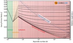
en-gases-liquids-fluid-mechanics-pressure-loss-pipe-friction-factor-moody-chart-diagram.jpg


As per moody chart i chose 0.023 approximately with the help of Re number.

then i tried darcy equation based on the below (my own) data

ΔP=f×(L/D)×(ρv2/2)

  • f=0.023
  • L=6 m
  • D=0.019 m
  • ρ=0.075 kg/m3
  • v=0.097 m/s
ΔP = 0.002563 Pa.

I considered pipe dia as 3/4" and length is 6 meters only upto vacuum pump.

i don't know whether is it correct or not but i just tried with the data you have given here and to learn from all of you.

Thank you.
 
@Asisraja D - Your general procedure makes sense, but there are a few items I believe you have got wrong. Bottled nitrogen is unlikely to be at 6.4 Kelvin. For gases the specific gravity is generally defined as the ratio of the molecular mass to that of air, so your value of 19.48 is strange. The kinematic viscosity is much too low. This might be because of the very low temperature you have used being beyond the limits of the correlation. Also check your density at 1.5 bara.

The section after the membrane needs to be calculated separately because there is a step change in pressure across the membrane.

In principle, using the Darcy-Weisbach equation (separately) for each pipe section is entirely reasonable because the density will not change much along the pipes - although it will change across the membrane and that is why the two sections need to be calculated separately.
 
Also your volumetric flowrate you've done at 1bara.

At 1.5bars it will be lower and at 65mbara it will be a lot bigger
 
Katmar sir
I did just basic calculations and do you think is this data op given here is enough for the calculations?
 
@Asisraja D - you have correctly identified the data required for this calculation but you have not got the correct values for that data. See also LittleInch's comment.
 
Thanks to all for your answers. I think the systems is well design. Pipe diameter is 1" and the needle valve is on the outlet side of your flow meter. There will be around 1 m pipe between membrane and pump. It is a good advice to work always in absolute pressure (i.e. 1.5 bar(a) in the inlet)

My main concern about this system is that I am "giving pressure" at the inlet, while "removing pressure" in the outlet, and there is a "pressure fight" in the membrane. How can we be sure that there is going to be positive pressure upstream the membrane and vacuum pressure downstream? If this were a system with a centrifugal pump, it would be clear for me that the operational point of the pump would be the intersection of the pump curve with that of the installation. Vaccum pumps have also characteristic curves, but it is not clear for me how to deal with them. Any advice on this? Pressure profile has a direct impact on the operating pressure to select the rotameter. Besides, maybe a vacuum brake would be necessary...
 
Hi Harvey,
I did not realize there is an "up and down" arrow to quote the posts.
I learnt something today! LOL
Fully agree with you
Pierre
Me too. I don't know if that feature is a good thing. Like katmar said if you disagree just say so in a post.
 
Hi,
It might be a miss manipulation trying to scroll down the threads.
My concern was about the lack of consistency between the sketch and the words, in particular Units.
My reading is that N2 pressure is 1.5 bar A at the inlet of the membrane and the delta P is (1500 -65) mbars . right?
Flow should be actual flow (T,P), not Normal condition to calculate the head loss.
Asisraja D, you may find good pointers in the document attached.
Good luck,
Pierre.
 

Attachments

  • A_Polytropic_Approximation_of_Compressible_Flow_in_Pipes_with_Friction.pdf
    664 KB · Views: 10
As pointed out by Pierreick and Snickster, the up and down voting system is a bit confusing if you have not seen it on other forums. Here it is even more confusing because we still have the old "Great post!" button as well and it is not immediately clear how the two systems complement each other. So it could well be that users have clicked either the up or down voting buttons by mistake.

But as Pierre has pointed out, I mixed up the absolute and gauge pressure values in my earlier post so it might well have been that someone was voting the post down because of the mistake. Unfortunately the edit option on my earlier post has expired so the error will remain there, but for anyone reading all the way through this thread please note that the 435 mbar that I mentioned as being the pressure drop across the membrane should have been 1435 mbar because the upstream pressure was given on a gauge basis.
 
No ones quite worked it out in terms of voting as we now have three....

In order I think of importance we have the up and down "vote" buttons which can be triggered in error by people just navigating the page, we have the "like" button which actually tells oil who liked it and then we still have the "great posf" button which I think gets you a star next to your post and in your profile.

About as confusing as this whole thread to be honest!
 

Part and Inventory Search

Sponsor