Continue to Site

Eng-Tips is the largest engineering community on the Internet

Intelligent Work Forums for Engineering Professionals

  • Congratulations MintJulep on being selected by the Eng-Tips community for having the most helpful posts in the forums last week. Way to Go!

Pressure required to shear screws. 2

Status
Not open for further replies.

CADCAMTech

Mechanical
Nov 10, 2015
33
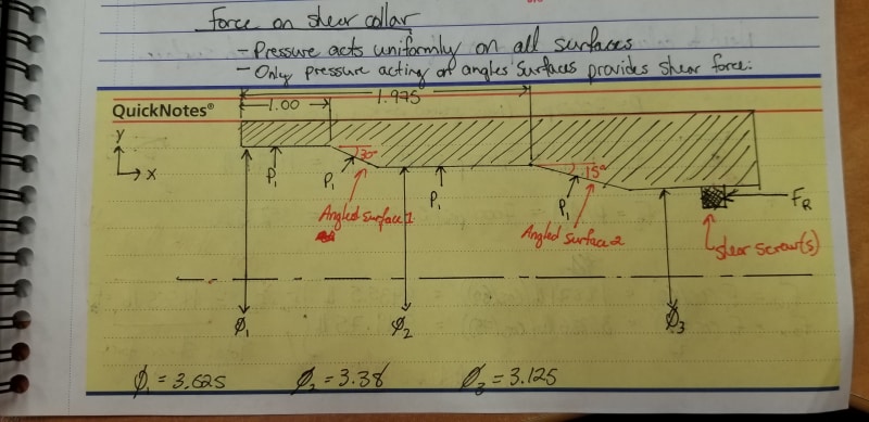
I am trying to calculate the amount of force that is applied to a fitting, when an internal pressure is applied to it. The red line shows the area where the pressure is applied, the blue dot is the shear screws, and the yellow arrow is the direction the fitting moves when the screw shears. The end goal is to calculate the number of shear screws I will need.

Sliding_Sleeve_j85wir.png


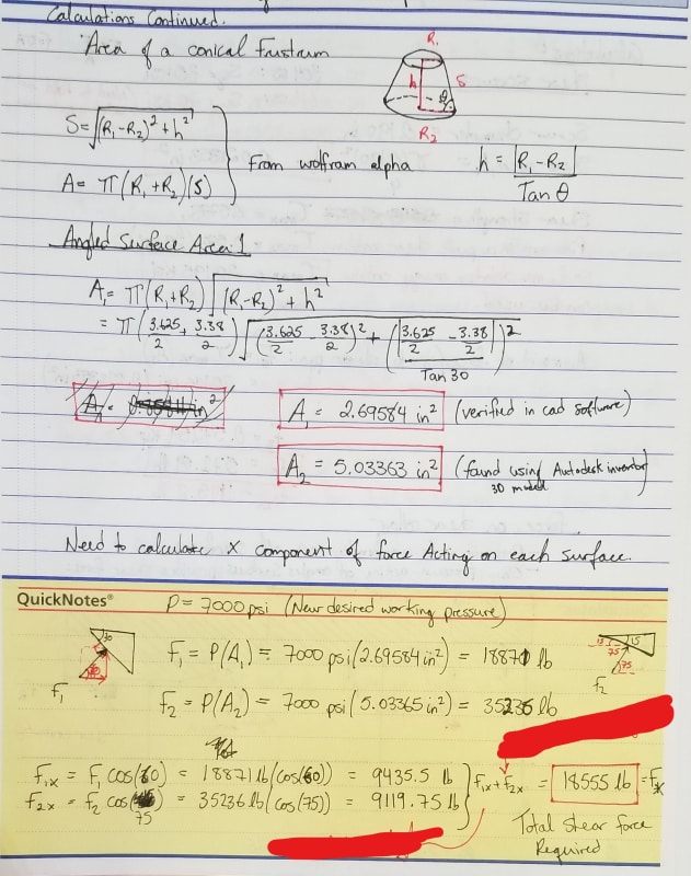
If you look at the attached images below you can see how I calculated the angled areas which I applied the 7000 psi pressure to. Then I calculated the force based on my known pressure and the known surface area with the pressure acting perpendicular to the surface, and finally I solved for the x direction of the force for each angled area.

The final value I ended up with (18871 lbf) was much larger than I was expecting and does not correlate with older data we have. Previous tests have shown that a pressure of approx. 3000 psi is needed to shear 3 screws, but this was all done by testing, no previous hand calculations exist for this product that I can find.

So I am wondering where I have went wrong:
1. When you look at F1 and F2 below, should I only be using the higher value instead of adding them together? To me both surfaces contribute to the force in the x-direction.​
2. I assumed that the max distortion energy criterion applied to the shear screws where shear=0.577Sy is this correct?​

If anyone is able to help point me in the right direction for what I am trying to do it would be appreciated, Thanks.

(to make things worse, I have no idea what the yield strength of the shears screws is. The drawing says it should be 304 SS at 35ksi min yield, but the PO I tracked down says the screws are 316 SS conforming to ASTM F880(CW) but no grade is listed and I have not been able to find out what that ASTM document specifies. I have hardness tested several of the screws and they seem to be around 96 HRB)
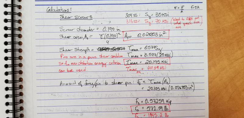
Shear_Screw_dz4pwn.jpg

Calculations_1_pvgbio.jpg

Calculations_2_hi5kr4.jpg
 
Replies continue below

Recommended for you

You need to use allowable shear stress on pins as per AISC.

Regards
r6155
 
You need to test them captive also, the two setups are different in how the screws will bend and shear.

= = = = = = = = = = = = = = = = = = = =
P.E. Metallurgy, Plymouth Tube
 
r6155,

You will have to explain why I should use the AISC specification, I will certainly have a look at it but I like to know why a certain formula or method is applicable. I have found several textbooks, documents, websites, and forums that discuss designing for shear stress. Ive listed a few examples below:

1. Maximum Shearing Stress Criterion = 0.5*Sy
Mechanics of Materials, 4th ed. (Beer, Johnston, DeWolf)

2. Shear stress using Maximum Distortion Energy Criterion = 0.577*Sy
Mechanics of Materials, 4th ed. (Beer, Johnston, DeWolf)

3. Maximum Shear Stress Theory of Failure = 0.5*Sy
Machine Elements in Mechanical Design 4th ed. (Mott)
(3 is from a section discussing key design)

4. Ultimate Shear Strength = 0.6*Ultimate Tensile
Inch Fastener Standards, 7th ed. (Industrial Fasteners Institute)

5. Shear Strenght = 0.6*Ultimate Tensile
Bolted Joint Design (Link)-Fastenal Engineering Document


I thought that AISC was strictly for structural evaluation of construction projects and not to be applied for mechanical systems. For mechanical system I use machine design guidelines.
 
CADCAMTech
This forum is Boiler and Pressure Vessel engineering. Your best choice is

Mechanical engineering other topics Forum

How to Determine max shear force on a pin
thread404-239817

I use AISC frecuently, this is excellent source for several mechanical design calculations, guides and examples.
See
Regards
r6155
 
R6155,

My initial question was a pressure vessel related question, but it has evolved into this now. I will move some of this over to the forum you suggest. As for AISC I have no doubt that it has good resources for mechanical design calculations but I was more interested in your reasoning for why it was a good place to get this information from.


EdStainless,

I can certainly create another jig to more closely represent the actual product by cutting a groove in it. I had made the assumption that the total length of the pin is very short and the actual shear plane is so close to the outside fitting that the amount of bending occurring before the shear failure was negligible. Was this a bad assumption?

Thanks,
CADCAMTech
 
CADCAM Tech said:
actual shear plane is so close to the outside fitting that the amount of bending occurring before the shear failure was negligible. Was this a bad assumption?

The diameter of the screws is so small that even a little offset in the shear plane will matter, by introducing more bending in the pin than you would see in your actual application.

You'll get the best possible result if the fit between parts in your test fixture is the same as the fit between your production parts.
 
CADCAMTech
The AISC Design Examples CD provides examples on the application of the 2005 AISC Specification for Structural
Steel Buildings (ANSI/AISC 360-05) and the AISC Steel Construction Manual, 13th Edition. The examples found
herein illustrate how the Specification and Manual can be used to determine solutions to common engineering
problems efficiently, and outline the background to many of the tabulated values found in the Manual.

This edition: 525 pag in pdf. you can see design of a pin.

Regards
r6155

 
I will just add that, in my experience, all shear pins that were intended to fail at a repeatable value had a square groove in them at the shear plane. This eliminates most of the variation caused by tolerances in fit between pin and hole, gap in the shear-plane, and radius of the edge of the hole, which will deform with a full diameter shear pin. This is particularly important if you intend to replace pins after they are sheared, because the hole geometry cannot be allowed to deform at all in such case.
 
Status
Not open for further replies.

Part and Inventory Search

Sponsor