Continue to Site

Eng-Tips is the largest engineering community on the Internet

Intelligent Work Forums for Engineering Professionals

  • Congratulations KootK on being selected by the Eng-Tips community for having the most helpful posts in the forums last week. Way to Go!

Pressure safety valve best practise

Status
Not open for further replies.

VladimirWH

Petroleum
Sep 20, 2019
18
Hello!
I have a question about calculating safety valve and inlet/oulet pipe.
I know there are a lot of informmation in this forum about it but not exactly what I need. The thing is I'm working in russia with russian standart (GOST). In present time i'm worjing in unusual project and have some difficulties with using GOST in this case. So I'm going to describe shortly problem:

Project - natural gas preparation station.
Preparation - drying, reduction seprartion by consumer.
To reduce pressure I'm designed simple scheme: valve-reduction valve-valve-safety valve.
Trouble is that diameter of run pipe DN200 and using our "safety valve standart" I need design inlet-outlet pipe and safety equivalent by run pipe.

Now I have oulet pipe DN300 (which our opinion is too big) because standart safety valve already have manufacturer standart Inlet/oulet connection (in my case DN150/DN300).
So wee see that it's excessive demands (for equivalent) and want to find a way to reduce size of it. Why we think like that? Because all station have alert and special safety systam with manual and automatic valve which turn off/on if something goes wrong and we don't need a safety with run pipe equivalent flow rate.

Question is: how it designed, I'm about safety valve and pipe calculating, in USA or Europe natural gas preapration station?

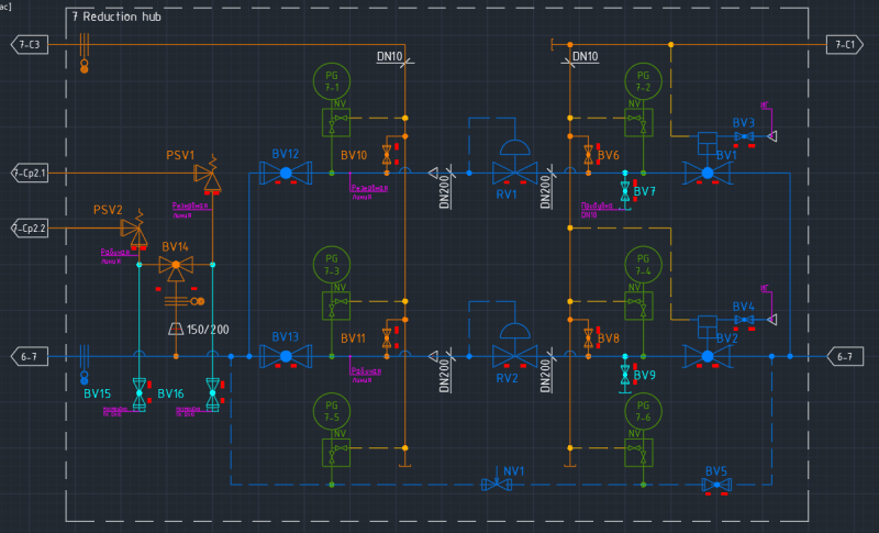
Here P&ID.
sample_bdtzto.png
 
Replies continue below

Recommended for you

I am not sure what you are asking.

Your PID shows 2 control valves RV1 & RV2 for downstream pressure reduction .
There are 2 automatic block valves upstream BV1 & 2, and manual block valves BV12 BV13 downstream.
It looks like there is a normally closed bypass , probably for maintenance purposes.
The downstream piping is protected from accidental overpressure by safety relief valves PSV1 & PSV2.
It looks like BV14 is a selection valve allowing use of PSV1 OR PSV2. So that is 100% redundancy.
Lines 7C1 & 7C3 are vent pipes to a safe location.
I do not know if both control valves RV1 and RV2 operate at the same time, or if only one operates alone, while the other is redundant spare.

Please correct my description, if I have something wrong.

The arrangement shown in the PID appears to be very typical of what is done in the west.
Having two relief valves, but using only one at any time is a little unusual. We would often have only one, but the number you install is a question of maintenance and repair convenience. It looks like you can repair one while continuing operation of the station. Very good.
Otherwise the arrangement is very typical. It is the recommended best practice in the west and safe to operate, because downstream piping is always fully protected from accidental overpressure. There are many different regulations in the west, so I am not sure, but I believe that the arrangement shown on your PID is required by local regulations in Germany and maybe other states as well.

I THINK you are asking about how to determine the size of the relief valves.
If only one relief valve operates at any given time, each valve must be designed for the greatest flow and highest pressure possible in pipe C6.7.
Due to the low pressure of the gas at the PSV outlet and usually a long distance to discharge at a flare, and the need to have low pressure loss, a large discharge pipe is usually required.

A typical calculation method for PSV sizing can be found here,

Please let me know if I have answered your questions.
 
1503-44 said:
Your PID shows 2 control valves RV1 & RV2 for downstream pressure reduction .
There are 2 automatic block valves upstream BV1 & 2, and manual block valves BV12 BV13 downstream.
It looks like there is a normally closed bypass , probably for maintenance purposes.
The downstream piping is protected from accidental overpressure by safety relief valves PSV1 & PSV2.
It looks like BV14 is a selection valve allowing use of PSV1 OR PSV2. So that is 100% redundancy.
Lines 7C1 & 7C3 are vent pipes to a safe location.
I do not know if both control valves RV1 and RV2 operate at the same time, or if only one operates alone, while the other is redundant spare.
Right, sir. RV1 and RV2 operates in different time (redundant spare).

1503-44 said:
I THINK you are asking about how to determine the size of the relief valves.
Right. Yeah, historically, in my department parametrs of safety valve and inlet outlet pipe choosing by manufacturer standart and run pipe diametr and always everything was allright, but now we have a problem with big safety valve and big outlet pipe. Most important that we haven't enough space because we made modular station, like 20ft container (Intermodal container) and two pipe DN300 above head when full celling high is 2.4 metr is awful.

Thank you for link, sir. I will look here. I have already found programm like that by Leser (valvestar).

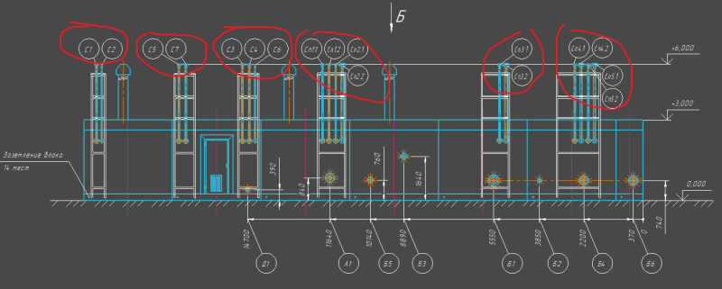
I add station view with flare (non-fire) for better understanding. Red circles are flare.

[
123_bzczwo.png
 
Vladimir,

I'm not sure if this is really your question, but generally PSV's inlet and outlet piping are sized based on the maximum pressure drop allowed for each (usually 3% for inlet and 10% for outlet @ PSV rated flow). Most of the times, the piping is larger than the PSV nozzles.

Daniel
Rio de Janeiro - Brazil
 
In addition to what Daniel said, the flow rate used for 3% inlet and 10% outlet pressure drop limits is the rated capacity of PSV at 10% overpressure; NOT the PSV sizing flow rate.

Good Luck,
Latexman
 
OK. You have short stack vents, no flare.

Actually DN 300 is relatively small diameter for many of these kinds of gas PSV station outlets. It would be nice to eliminate PSVs, but then the downstream piping would not be positively protected from overpressure. I am not a big fan of "HIPSS", high integrity protection safety systems that sometimes are used to eliminate PSV and vents, because it increases the maintenance and testing work while safety and reliability is decreased. HIPSS are not prohibited by ASME B31.8 or EU gas codes, but they may be prohibited by the various national regulations, or company specifications. You must know the state and local regulations and also be sure that they are allowed under company policy. PSVs are much safer. A large explosion and many building fires were started near BostonMA, USA a few years ago, with over $1E9 in damages, because PSVs were not installed at a pressure regulation station.

 
Vladimir,

I think what you're trying to do is reduce the size of the outlet pipe?

You need to look at the back pressure of the relief valve at full flow. For conventional spring relief valves this is usually max 10% of set pressure.

Balanced bellows relief valves I think allow this to increase to 30% - check it out.

Also the inlet pressure drop can be higher than 3%, but then you need another tapping and run the relief valve with a pilot operated relief valve.

how and what size your relief valve needs to be is a complex assessment and what impact having gas pouring out of avent does for you.

Spring operated relief valves are very reliable and have the impact of generated a high SIL (safety Integrity Level) number. HIPPS (not HIPSS) systems try to replicate this reliability using things like two out of three voting on sensors, high reliability components and high reliability software and control devices. But they cost a lot and a simple spring relief valve doesn't.

But learn more about the different types of relief valves if you want to reduce the size of your vent. But also look at noise and velocity. A high Mach number generates huge amounts of noise.

Remember - More details = better answers
Also: If you get a response it's polite to respond to it.
 
danschwind, Latexman thnak you for answear.

1503-44 said:
A large explosion and many building fires were started near BostonMA, USA
It's a horrible incident.

LittleInch said:
I think what you're trying to do is reduce the size of the outlet pipe?
Yes, sir. How I said, usually we design station with much lower flow rate, but in that project we have trouble with big safety valves.

I with collegues think that the best thing use relief valve with safety overpressure shut-off valve. We ready to lose some stable flow for consumer but no need to use big system with safety valves and threeway valve.
 
Vladimir,

I suggest you to stick with simplicity here. A HIPPS system capable of handling this scenario is probably way more expensive than the PSV's and its piping.

Remember: your system must be able to handle the overpressure before anything starts rupturing.

There maybe other things that can be done though, like reviewing the control valve sizing.

Daniel
Rio de Janeiro - Brazil
 
You might ask your customer if they are prepared to accept the possible consequences, the expense and extra maintenance and routine testing requirements.

What does GOST require in these installations?


VladimirWH,
Most design companies provides a Data Sheet (based on inhouse PRV sizing Application) to the PRV Vendor who in turn will refine the sizing calculation in their own proprietary application and offer the final speciation.

GDD
Canada
 
VladimirWH,
If I understand your concern correctly, you want to reduce the the size of the PRV for less demand.
Of course you can resize the valve. The most critical part of PRV design is determining the rated relieving capacity. The PRV must relieve a sufficient quantity of fluid so that the pressure in the system never exceeds the specified overpressure (which in your case will be GOST). ASME Code requires capacity certification of relief valves,
The rated capacity of the PRV must be greater than the required capacity determined form the worst case system failure scenarios.
Once the PRV is sized for rated capacity and pressure, you will be able to easily determine the inlet/outlet pipe sizes, which again you should be guided by GOST.

GDD
Canada
 
Your first post states a PRV size of inlet/outlet of DN150/DN300. That outlet size is quite large relative to the inlet size. Typically following API-526 Standard, the PRV size would be 6" x 8" (DN 150 x 200) or 6" x 10" (DN 150 x 250). How have the PRV's been sized and selected?

*** Per ISO-4126, the generic term 'Safety Valve' is used regardless of application or design ***

*** 'Pressure-relief Valve' is the equivalent ASME/API term ***
 
1503-44 said:
What does GOST require in these installations?
100% reservation by flow rate

GD2 said:
form the worst case system failure scenarios.
Yeah, but mostly costumer refers to a GOST document, it's mean 100% reservation by flow rate

The Obturator said:
How have the PRV's been sized and selected?
By supplier calculation and his basic model range.

I want to thank all of you. And, how I said, the main cause of my problem is regulating documents and sometime useless increasing requirment by safety valve rate for my view.
 
Vladimir, your last comment regarding sizing and selection by PRV vendor, suggests the Pressure-relief Valves are of a vendor standard and not particularly following well known norms. The outlet size is very large and generally non-standard. Do you have data sheets available for the PRV's - I can at least run a sizing calculation and make a recommendation of what should be offered/expected?

*** Per ISO-4126, the generic term 'Safety Valve' is used regardless of application or design ***

*** 'Pressure-relief Valve' is the equivalent ASME/API term ***
 
Try asking the vendor for his balanced bellows range and see what the size of the vent pipe reduces to.

"Basic Range" will get you "basic sizing"

Remember - More details = better answers
Also: If you get a response it's polite to respond to it.
 
The Obturator said:
I can at least run a sizing calculation and make a recommendation of what should be offered/expected?
Thank you, sir, for the offer but now It's not so necessary.

Maybe I was wrong when I said about DN150/DN300. So I wiil calculate it by myself and if I have a question I write.

LittleInch said:
Try asking the vendor for his balanced bellows range and see what the size of the vent pipe reduces to.

Ok, thank you.
 
Status
Not open for further replies.

Part and Inventory Search

Sponsor