Eng-Tips is the largest engineering community on the Internet

Intelligent Work Forums for Engineering Professionals

Pressure Vessel Pipe Spool 5

Status
Not open for further replies.

KevinNZ

Mechanical
Jun 12, 2003
827
0
0
NZ
A customer is installing a custom pipe spool within a piping system, simple flanged 'spool' as below. Different material (thicker and higher allowable stress) to the piping. The problem is they require the spool to be designed as a pressure vessel (ASME VIII-1) rather than a pipe spool. Now as the piping designer how do we show the 'nozzle'/body loads from the piping are OK to the vessel code? Any shortcuts? Can we just say the piping stress will be higher than the spool and piping calculations are no less conservative than ASME vessel calculations?

The spool/vessel designer is not being supplied any piping loads, so we will not be getting the calculations from them.

Trying our best to convince the customer to change to the piping code and we just include the spool in the piping stress model.

Screenshot_2024-07-03_130742_gqhnkp.png
 
Replies continue below

Recommended for you

It’s responsibility of the piping designer to receive the actual design condition of the “ASME BPVC pipe” from the responsible Vessel Engineer to ensure that the connecting B31.1 piping are properly specified. Don’t assume anything if something is not clear or lack of information.
 
MK3223 thanks for reply
We are have drawings of the "vessel" but with no allowable nozzle/flange loads. The piping is existing so we can not change the pipe. Just need to show the spool/vessel passes code when installed.

We do know for sure the spool is OK if was piping.
 
I don't think you can.

Vessel codes and stresses are different to piping.

Can't understand why this is a vessel, nor can I understand why you didn't supply loads to the vessel designer from your stress analysis??

Remember - More details = better answers
Also: If you get a response it's polite to respond to it.
 
KevinNZ, if you are forced to stay with VIII-I, UG-44(b) has guidance on external loads on standard weld-neck flanges. You may find it useful to specify allowables. Or not :)

Regards,

Mike

The problem with sloppy work is that the supply FAR EXCEEDS the demand
 
Note that Code Case 2901 has been revised under ASME BPVC C.C Supplemental 4 and might be a better option for design those flanges.
 
OP,
Had a similar situation, may or may not apply. A customer needed a have a venturi fabricated for a steam line. Was it composed mainly of standard piping components? yes, but both the entrance and exit nozzles required fabrication. Because of this, a method for design and fabrication was required. The customer decided to use the BPVC as the guidance. Was this a stamped asset? no, it was just requested so the design and fabrication had known conformity. This may be why your customer is requesting this. It also may be as simple as your customer doesn't want a spool piece that doesn't match the rest of the piping's specification, so they are viewing it as a piece of equipment instead of a standard spool.
 
As the piping designer I would perform the stress analysis considering the spool is just part of the piping using the actual wall thinkness and material allowables of the spool per B31.1. If the stress analysis passes B31.1 requirements then it is OK. They can design the component to be put in the piping to any pre-qualified code or standard allowed by B31.1 but it would still be considered part of the piping.

Piping codes allow components installed in lines to be designed per different codes such as codes for valves, fittings, strainers, etc., and venturies mentioned by Heavyside above. That does not mean they are not part of the piping. Strainers and other components are sometimes designed per ASME B&PV Code as an option of the manufacturer if you want a very heavy duty construction. This does not mean when you install it in the piping you need to analyses the nozzle loads like you analyze a real pressure vessel nozzle loads. No you would just do a piping stress analysis of the piping and model the strainer as a rigid and if the piping stress passed you would assume that the load in the rigid was OK too assuming it is stronger than the piping. What else can you do as you cannot re-evaluate the entire design of the strainer with the piping loads included. You don't even have the original manufacturer's calculations for the strainer.

Besides the nozzle of a real pressure vessel is nothing like a nozzle of an in-line piping component where the nozzle in your case is the full size of the piping. In a pressure vessel nozzle you are analyzing the local stress in the vessel wall due to forces and moments at the nozzle. In your case the situation is totally diffrent and the loads are transfered not to the wall but to the entire structure of the in-line spool just like a piping component. So I would analyze it just as a piping component. As the design engineer of record who is stamping a design I believe you have the authority to make such engineering decisions when you are confronted with non-straight forward cases.
 
As being pipe stress and vessel designer for years, none of the above replies are correct, or shall say only partially correct.
Any pipe or spool can be treated as vessels for specific reasons. I have done 12", 18", 24" pipe as vessels with code stamp. However, stamp is not mandatory if client is ok with that. It can comes with top ,bottom or body flanges, very common and not a big deal, same as the spool.

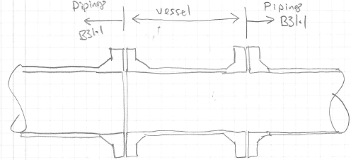
Snickster you are correct to model as B31.1 for the spool, which is very common to do so and shall do so. But you are not correct when a pipe spool is treated by a vessel code. You can only qualify up to the B31.1 mating flange, but for the body flange on the pipe spool, you will need to use UG-44(b) or equivalent pressure method to qualify. Equivalent pressure method is much more conservative than UG-44(b). Either method is fine. Keep in mind the equation in UG-44(b) is not mandatory. So many people have the wrong impression that that equation is mandatory. It is not. You can use other approaches to prove your flange is good for internal pressure plus external loading. CAESAR II has built-in function to check flange rating with external loading, which is completely different from UG-44(b) and we accept it such that vessel supplier does not need to perform UG-44(b). This is another simple concept but I won't waste time to address here.

For the pipe spool itself, since it will be treated as vessel, then must obtain the longitudinal tension and compressive stresses and compare with Section II, Part D and B factor compressive allowable respectively. If wind/seismic is included, the allowable stresses can be increased by 20%. The vessel code calculation is much complicate than B31.1 or B31.3.

So Kevin, get the external loading at the face of flange, and get a guy who is familiar with vessel code, and either model into PV Elite or Compress, or by hand calculation. This spool is very simple, hand calc can be done to check spool thickness due to internal pressure, the maximum longitudinal tension and compression stresses due to internal pressure (PR/2t), axial force and bending moment acting at the face of flange, than compare with two different allowable. Also to qualify the flange rating per UG-44(b). Very simple, not a big deal.


JT1234

I agee that you should check the flanges per the equivalent pressure method which is included as a subprogram of Caesar. This is typically done for all in-line flanges.

If you think the spool must be analyzed strictly as a pressure vessel then I would do the piping stress analysis and provide the nozzle loads to the manufacturer of the spool. They are designing the spool to ASME so I would let them take full responsibility for the design. I would not take responsibility for a pressure vessel design calculation for a vessel that was designed and provided by others.

I don't know but it seems you are trying to kill a fly with a hammer, but honestly I am not sure what is legally the absolute correct way to proceed.
 
It appears the OP has no knowledge of the applied loads. If so and if the spool uses standard weld neck flanges:

1) Spool cylinder is thicker and of higher allowable than adjacent piping. By inspection cylinder is adequate for loads imposed by the piping.

2) Flanges: evaluate right hand side of equation UG-44(b)(4) equal to, say, X. Inform customer that the left hand side, 16Me + 4FeG ahall be <= equal to X.

MAWP of the spool is easily found from Sec VIII Div 1 and flange rating.

Anyway that was kind of my thinking in offering up UG-44 :)

The problem with sloppy work is that the supply FAR EXCEEDS the demand
 
Hi all, thanks for the input.
Some more context. The spool is DN350 class 300 WN flanges. 10mm wall 2205 stainless (CA 0.5mm). The piping is CS STD 9.52mm (CA 3mm). Design pressure well below full class 300 rating. We have the full piping model and the loads at the flanges. The purchaser has not given these to the spool/vessel vendor/designer.

Engineering logic says the spool is fine if the piping each side is OK. But the miss match of codes is the problem. Looks like someone is going to need to do the ASME vessel and flange calculations to complete the loop, no shortcut? or we could get agreement with the client (and inspector) to redesign it as a pipe spool.
 
What is you roll in all of this. Are you not working as engineer for the purchasing company? I guess a lot depends on what is your liability and responsibility in all of this.
 
Hi,

Refer to U-1(c)(2)(-d), I think that is worth trying to use this paragraph to convince the customer that the spool shall be designed using one of the piping Codes.
 
Wait a minute guys.
No one is talking about if it is an option to design the spool as pressure vessel to Sec VIII Div 1? Typically, a pressure vessel will have a cylindrical body with two end heads and openings.

In our spool case, the cylindrical shell (DN 350) will have both ends with full opening.

Can someone highlight the rules of Div 1 paras that the spool can be designed as a pressure vessel? Once it is viable, the loadings from the two B31.1 piping on the spool is not an issue and many members have talked about it.

GDD
Canada
 
ASME VIII DIV 1
U-1
(a) See below. (1) The Foreword provides the basis for the rules described in this Division. (2) For the scope of this Division, PRESSURE VESSELS ARE CONTAINERS for the containment of pressure, either internal or external. This pressure may be obtained from an external source, or by the application of heat from a direct or indirect source, or any combination thereof (a)

U-1
(2) Based on the Committee’s consideration, the following classes of vessels ARE NOT INCLUDED in the scope of this Division; however, any pressure vessel which meets all the applicable requirements of this Division may be stamped with the Certification Mark with the U Designator: ….....
(-e) piping components, such as pipe, flanges, bolting, gaskets, valves, expansion joints, and fittings, and the pressure-containing parts of other components, such as strainers and devices which serve such purposes as mixing, separating, snubbing, distributing, and metering or controlling flow, provided that pressure-containing parts of such components are generally recognized as piping

I insist: PRESSURE VESSELS ARE CONTAINERS. This spool is not a container and ASME VIII div 1 is NOT APPLIED.

Regards
 
Status
Not open for further replies.
Back
Top