Eng-Tips is the largest engineering community on the Internet

Intelligent Work Forums for Engineering Professionals

Primary to Secondary Datum Structures 1

Status
Not open for further replies.

PRuggiero

Mechanical
Oct 8, 2007
64
0
0
US
I'm making my head hurt because I think i'm making something harder than it needs to be.

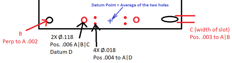
I have a Circuit board that interfaces with a heatsink through two pins (part of the heatsink) with a hole (Datum B) and slot (Datum C defined by the width). There is a pattern of holes (two Ø.118 and 4 smaller ones) that are for a connector. This is all shown in picture 1.

Link

It is more important for the connector holes (really the Ø.118 ones) to be oriented to the A|B|C datum structure than it is to be located.

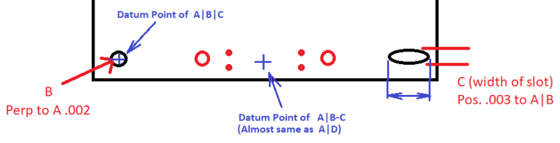
Picture 2 seems to make the most sense to me with respect to accomplishing my goals.

Link


Picture 3 is what i am more used to seeing, what I don't understand is how this controls the orientation relationship between B-C and D-E since Datum E is only positioned relative to A|D.

Link

Thoughts/Feelings?


Thanks,
Pete
 
 http://files.engineering.com/getfile.aspx?folder=0f7806fb-31b5-4291-b840-64efecc4a1ee&file=3.png
Replies continue below

Recommended for you

What exactly you mean by "orientation to A|B|C"?
Because the only orientation I can see here is perpendicularity to A.

"For every expert there is an equal and opposite expert"
Arthur C. Clarke Profiles of the future

 
Meaning the planes defined by B and C are oriented to the planes defined by D and E. In other words right now if you draw a line between B and C and another line between D and E the angle between the lines is 0. In real life that won't be the case, right?
 
This way it still position.

Your picture 2 is the closest thing, although I am not sure if there is the need to introduce more datums into it.

If you could clarify relation between .118 and .018 holes, we could come up with more detailed solution

"For every expert there is an equal and opposite expert"
Arthur C. Clarke Profiles of the future

 
Assuming I understand the design intent correctly, I would say that your picture 2 is almost what you need. However, if the two .118 holes play equal role in locating and orienting the connector, I would probably make them pattern datum feature D (instead of separate holes D and E) and control the remaining four small holes with position to A primary and D secondary.
 
I can also see loose Position to A|B|C and tight position to A applied to both sizes of holes.

That will make them one "connector" pattern.

If "tilting" of "connector" to the board still critical, I would add single control to A|B-C to control how much holes can play up and down.

(All that provided all holes are located using basic dimensions)

"For every expert there is an equal and opposite expert"
Arthur C. Clarke Profiles of the future

 
If D was a datum of the two holes, how exactly does that get inspected?

Checker, what would be the point of doing a|b-c vs just a|b|c?
 
Code:
If D was a datum of the two holes, how exactly does that get inspected?

Picture_1-31-18_ertza4.png


As long as you know where is the datum point, you will know how to measure and inspect the position of the four small holes.

Code:
what would be the point of doing a|b-c vs just a|b|c?

Picture_1-311-18_pbxiuk.png


Please let me know if any missing

Season
 
B-C establishes "a line between B and C". "Just A|B|C" will override your "loose" A|B|C requirement.

To be honest, if all your holes are made "at once", from the same punching / drilling operation you probably don't need all that elaborate scheme.


"For every expert there is an equal and opposite expert"
Arthur C. Clarke Profiles of the future

 
I like the idea of having Datum D be represented by the two holes, I think I would do a composite tolerance there to control orientation tighter than location. My only hesitation with this method would be someone (vendor) making the part mis-interpreting it to be that Datum D is the one hole where the arrow goes....
 
 http://files.engineering.com/getfile.aspx?folder=d8e07e08-7454-4724-b33a-94579a0ef67e&file=5.png
We have measurement software (not cheap either) that cannot handle a pattern of holes being a datum feature. This software has absolutely no problem using a single hole as a datum feature and another hole as a clocking datum feature. I had to change the datum scheme of a part due to this. Make sure you speak with your quality team before finalizing your scheme.
 
If the holes on the picture are mounting holes, that is, have some solid objects coming thru, the entire set-up could be checked with fairly simple functional gauge(s).

"For every expert there is an equal and opposite expert"
Arthur C. Clarke Profiles of the future

 
Status
Not open for further replies.
Back
Top