Eng-Tips is the largest engineering community on the Internet

Intelligent Work Forums for Engineering Professionals

Problem about Yield and Tensile Stress of SUS310S and SUS316 at 850 Celsius 9

Status
Not open for further replies.

Quentin Nguyen

Industrial
Apr 20, 2023
14
0
0
VN
Dear Engineers,

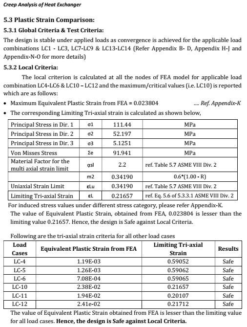
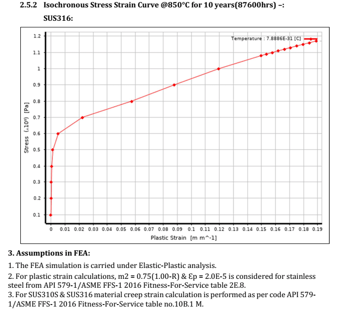
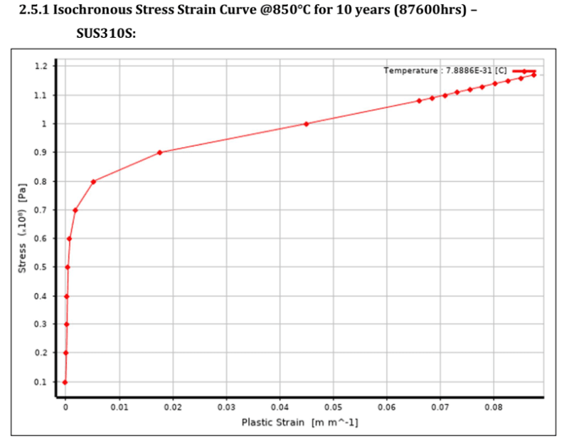
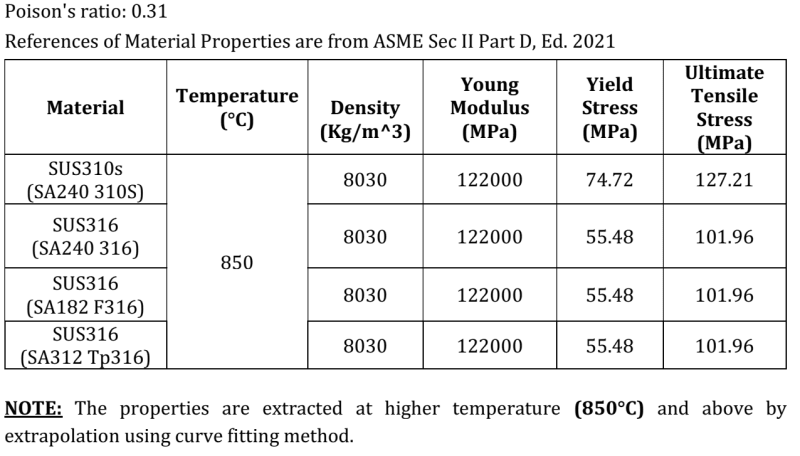
I am running into a problem finding or calculating Yield Stress (MPa) and Ultimate Tensile Stress (MPa) for SUS310S and SUS316 using ASME Section II Part D to match the table as attached.
Screenshot_2023-08-22_150910_ap3fyd.png


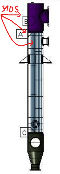
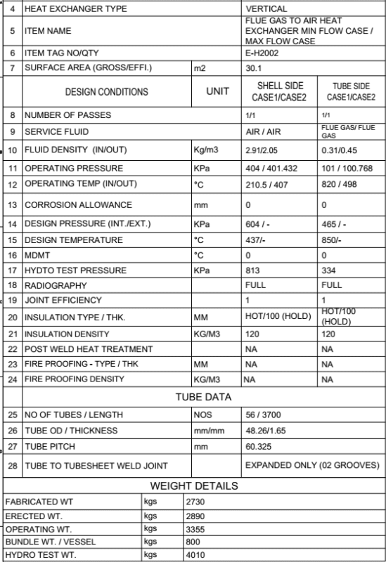
I am running FEA based on ASME Section VIII Div.2 Part 5.3.3 - Elastic-Plastic Analysis for a Heat Exchanger. Mechanical Datasheet as shown in the photo below.
Screenshot_2023-08-22_151231_gtofhq.png


Although, can anyone please show me why SUS310S yield and tensile are larger than SUS316 because based on my calculation using ASME II D, SUS310S yield and tensile shall be smaller than SUS316?

Thank you so much!
Regards!
 
Replies continue below

Recommended for you

A couple of thoughts:
1) These values exceed the reported values in ASME Section II, Part D (Metric). The maximum temperature for these values is 825°C.

2) The first table that you show, says "Note: The properties are extracted at higher temperature (850°C) and above by extrapolation using curve fitting method." You would be best to ask the creator of that table to understand two things: a) how do they think that it is permitted, from ASME Section II, Part D, to extrapolate beyond the values provided in Table Y-1 and U? What "curve fit method" is used for this extrapolation and is there a published reference for that method?

3) These temperatures are well into the creep regime. For example, the 310S material has its allowable stresses governed by time-dependent properties at and above 525°C. Therefore, at the 820°C tubeside inlet temperature, you are 295°C into the creep regime. Any sort of elastic-plastic analysis that you would be doing, whether it is 5.2.4, 5.3.3, 5.4.3, 5.5.7, or 5.5.4, are all predicated on NOT being in the creep regime.

Can you please provide a bit more information on exactly what you are trying to accomplish?
 
Thank you for your reply, TGS4!
Sorry for my bad English.

My task is to confirm that we can use SS310S and SS316 for this Heat exchanger (HE) to run normally for at least 10 years. I have an old strength report for this condition using elastic-plastic analysis method based on ASME VIII Div. 2 part 5.3.3 and API 579 ASME FFS. FEA software was ANSYS.

This HE will get PED certificate so I think it does not need the permit from ASME, they just use ASME material. But the number must be as close to right as possible so that we can have the most accurate result. In table Y-1, ASME II D 2023 metric line 28, Sy of SA-240 310S at 825 Celsius is 46.6, and as I know it shall not increase if the temperature increase, so there is no chance for Sy=74.72 MPa at 850 C. Please correct me if I am wrong.

As you can see, in the photo is the design of this HE with the upper tube side, upper tube sheet and tubes are SS310S. The other parts are SS316.
Screenshot_2023-08-23_080757_sfq0yv.png


And this is the conclusion in their result. I can send you a full report if necessary.
Screenshot_2023-08-23_081639_hi4u9v.png


Currently, I knew that it must be time-dependent apply to yield stress and other characteristics of those materials in use. And the report is using 87600 hrs constant for 10 years to build the stress-strain curve as shown below.
Screenshot_2023-08-23_084241_ejx2vp.png

Screenshot_2023-08-23_084212_m3syak.png


I also did some extrapolation using some trending lines in excel but the results were not close to the table. The Y and U of 310S is smaller than 316 always. But I figure out that SS310S can handle higher temperature service than SS316. But so far, I cannot prove that base on stresses in ASME II D.

I am kind of stuck because this is my first time trying to understand this method, so it is really grateful that anyone can help.
 
It appears that whoever performed this work used the equations in Table 2E.4(M) and Table 2E.6(M) from API 579-1/ASME FFS-1. However, your temperature of 850°C exceeds the applicability maximum of these equations (the maximum temperature for these tables is 816°C.

I calculated the isochronous curves for these materials for these temperatures and this time. I get absolutely nothing like the curves that you show.

Just as a note, the yield and ultimate strengths are a distraction at these temperatures - the behaviour is completely creep-governed. You really need to push back on whomever performed this work - it is extremely troublesome and potentially dangerous.
 
Quentin,

TGS4 is proving you with some fantastic input.

Have you considered using SA240 347, 321 etc. for better creep strength?

Check BPVC section I, III etc for listing and allowable temperature limits.

GDD
Canada
 
And don't forget 310H as well.
What material are the tubes and tubesheets?
At these temperatures you probably don't want just rolled joints.
At least a seal weld with the roll.

= = = = = = = = = = = = = = = = = = = =
P.E. Metallurgy, consulting work welcomed
 
Thank you so much for all the help! TGS4, GD2, EdStainless
TGS4 said:
It appears that whoever performed this work used the equations in Table 2E.4(M) and Table 2E.6(M) from API 579-1/ASME FFS-1. However, your temperature of 850°C exceeds the applicability maximum of these equations (the maximum temperature for these tables is 816°C.
I am now know exactly where they get those numbers for Y and UTS thank to TGS4. Really appreciate that.
So what if I want to calculate for the temperature above 816C, where should I take the input to do FEA?

TGS4 said:
I calculated the isochronous curves for these materials for these temperatures and this time. I get absolutely nothing like the curves that you show.
Could you please show me how to draw the curve by hand? I am quite sure that those curves in the report were taken from ansys. I did it myself a couple of times, but still can't. Thinking I don't understand the method yet.

And sure, from now I will try to contact with the person who did that report for more information. It is kind of risky for me now to take the responsibility.

If my final conclusion is "reject 310S", then I will consider other material for the upper tubeside, upper tubesheet and tubes as you guys told me. Really appreciate.

My best regards!
 
The isochronous curves are generated using the equations in API 579-1/ASME FFS-1 Annex 10.B. You should be able to generate them yourself using Excel or Mathcad (or equivalent). I would ignore any refence to "ANSYS" or other software. These curves are inputs to an analysis, not outputs - so don't allow yourself to be fooled thinking that they came from FEA software.
 
Quentin,
My further comment on the design:
1. Why is there a big jump in the Design Pressure? 101 Kpa Vs 465 Kpa -Tube side. Is plus 103 Kpag (25 psig) not good enough?
2. I did some research on material useabilty. Limiting design temperature for 316H/347/321H is 815C. Limiting design temperature for Alloy 800H/HT is 954C.
3. Temperature Limit for Creep design (borderline from elastic to creep): 316/347/321H - 538C, Alloy 800H/HT - 565C.

The information in 1 and 2 implies that the HX should be designed for both elastic and creep rupture.

4. Allowable stress for rupture design is dependent on rupture strength and service life intended. Elastic design allowable can be taken from Sec II part D stress tables.
5. For rupture design, you can follow API 530 and WRC 541.

Essentially, your design codes will be ASME Sec VIII Div1, API 530, WRC 541 for this high temperature service.

The other option will be to do a heat transfer analysis to determine the design metal temperature and see which parts will fall under creep and elastic design.

Obviously, API 579 do not do any material selection and simply provides an assessment solution.

GDD
Canada
 
TGS4 said:
The isochronous curves are generated using the equations in API 579-1/ASME FFS-1 Annex 10.B. You should be able to generate them yourself using Excel or Mathcad (or equivalent). I would ignore any refence to "ANSYS" or other software. These curves are inputs to an analysis, not outputs - so don't allow yourself to be fooled thinking that they came from FEA software.
Thanks for your advice, I will draw the curve again following Annex 10.B, try to understand the method. Since I couldn't draw it by hand, the software helped me with this right after I typed the properties of the material in.

Dear GD2,
GD2 said:
1. Why is there a big jump in the Design Pressure? 101 Kpa Vs 465 Kpa -Tube side. Is plus 103 Kpag (25 psig) not good enough?
This input data is based on the process data of the factory. I couldn't change that since the outlet of other processes will be the inlet of this.

GD2 said:
2. I did some research on material useabilty. Limiting design temperature for 316H/347/321H is 815C. Limiting design temperature for Alloy 800H/HT is 954C.
3. Temperature Limit for Creep design (borderline from elastic to creep): 316/347/321H - 538C, Alloy 800H/HT - 565C.
I agree with you that other materials may have higher temp. limit and better creep handle. But this is my task right now to calculate this HE using 310S and 316.

GD2 said:
4. Allowable stress for rupture design is dependent on rupture strength and service life intended. Elastic design allowable can be taken from Sec II part D stress tables.
5. For rupture design, you can follow API 530 and WRC 541.

Essentially, your design codes will be ASME Sec VIII Div1, API 530, WRC 541 for this high temperature service.

The other option will be to do a heat transfer analysis to determine the design metal temperature and see which parts will fall under creep and elastic design.

Obviously, API 579 do not do any material selection and simply provides an assessment solution.
Thanks for your advice, I'm currently using elastic-plastic analysis to design this HE. I will look through API 530, WRC 541 for more information.

This is my first time running into high temperature service. I need to understand more about time-dependent and service life affect to this HE and how to calculate and write a full report.
 
I have read through API 530, WRC 541 and calculated the time-dependent allowable stress and minimum thickness due to Rupture Design With Constant Temperature. But they only available to 1500F.

I just need to confirm that it can operate in 10 years within the input above. I think I'm going to dig deeper in design by analysis and FEA to get the result.
If any of you can give me some advices, it would be my pleasure. Thank you!
Best regards!
 
If you operate at the design temperature of 850°C, no, you will not last 10 years.

What is the actual operating metal temperature?
 
Quentin,

I got couple of questions for you again:
1. You have done an elastic-plastic analysis per 5.3 rules of Sec VIII -Div 2. This analysis do not take into consideration the creep strain rate. It's only a inelastic plasticity.
1. What is the maximum temperature limit in table 5.7 for 310S for the strain limit?
2. If you haven't considered the creep strain, obviously your Isochronous stress-strain curves can go wrong.

In summary, first and foremost, the material selection of tubeside 310S is wrong.

TGS4 had directed you in the right direction from the start.

GDD
Canada
 
TGS4 said:
What is the actual operating metal temperature?
It is 820 C Flu gas input Tube side.

GD2 said:
1. What is the maximum temperature limit in table 5.7 for 310S for the strain limit?
The table is limiting 480 C for stainless steel. It is the lowest temperature limit. It's not even reached the creep temperature of SA240 316. Could you please explain that? Thank you.
 
Yes it can, in a heat treat basket where the stress is about 0.5ksi.

= = = = = = = = = = = = = = = = = = = =
P.E. Metallurgy, consulting work welcomed
 
Quentin,

Don't get disheartened but I would say your assessment is wrong on wrong material selection, wrong analysis based on ASME BPVC Sec VIII Div 2, 5.3 that don't account for creep.

GDD
Canada
 
Status
Not open for further replies.
Back
Top