Continue to Site

Eng-Tips is the largest engineering community on the Internet

Intelligent Work Forums for Engineering Professionals

  • Congratulations waross on being selected by the Eng-Tips community for having the most helpful posts in the forums last week. Way to Go!

Problem in Modal analysis 1

shiv22111993

Student
Nov 7, 2024
3
Hi ,
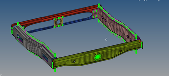
I am performing modal analysis of an assembly in a free-free state. I am getting only 5 rigid body modes instead of 6. I have tried many things, but it didn't work . I am attaching .bdf file. Please help me resolve my problem.
 
Replies continue below

Recommended for you

not going to dig thru a bdf file. suggest you post a picture of your model, with the constraints and loads shown. which rigid body mode is missing?
 
The eigenvalue table you see at the end of the job is obtained from an analysis which detected a massless mechanism. The one massless mechanism was constrained, and in doing so it looks like it removed a rigid body mode.

Lesson 1: Read the messages in the f06 file.

Immediately prior to the eigenvalue table, there are 2 important messages:

*** USER INFORMATION MESSAGE 9119 (SUBDMAP MMFIND1)
1 RIGID BODY MODE(S) AND 1 MASSLESS MECHANISM(S) ARE DETECTED.
^^^

^^^
*** USER INFORMATION MESSAGE 9146 (SUBDMAP MMFIND1)
THE FOLLOWING DEGREES-OF-FREEDOM ARE CONSTRAINED TO PREVENT MASSLESS MECHANISMS DURING EIGENSOLUTION.
^^^

The eigenvalue analysis attempted a shifted problem 3 times (see messages prior to these 2 messages), before it gave up and the massless mechanism logic took over. The resulting eigenvalue table is not intended to be used for any other purpose than telling you that you have a problem in your model, and this problem turns out to be one fewer rigid body modes than you expected.

Massless mechanisms are exactly what they say they are. The eigenvalue problem requires 2 inputs, stiffness and mass. If somewhere in the model both these quantities are zero and the degrees of freedom (DOF) where this occurs are not coupled to anything else in the model, then how do you compute the ratio of K/M?

Finding massless mechanisms in a model, when all you have is a 2 dimensional array of stiffness and mass is a numerically intensive problem, and with the MSC Nastran version you are using will only tell you how many of these massless mechanisms there are in the model. It does not help you much to diagnose the root cause.

However, with a little detective work (more f06 reading), you can look for other clues. For example, I noticed a bunch of GRID points in the GRID POINT SUNGULARITY TABLE where all 6 directions have “FAILED” stiffness ratios. That is suspicious. If directions 4,5,6 fail, then this may well be associated with the rotational DOF of solid elements, but there is no guarantee of that. However, any DOF failing in directions 1,2 or 3 should be treated as suspicious if it is not intended behaviour. The bdf file defines PARAM,AUTOSPC,NO – this means any degrees of freedom in the model where there is zero stiffness will not be removed automatically by the program, so those GRID points failing in DOFs 1 thru 6 (specifically GRID points 2264, 2369 thru 2381, 12367 thru 12369 and 14426 thru 14428) should be removed from the model as they have nothing attached to them.

Lesson 2: Read the messages in the f06 file. Check the GRID POINT SUNGULARITY TABLE for any suspicious “FAILED” directions; if AUTOSPC is set to NO, ask yourself why and if retained with this value, you should think carefully about this table’s information.

Finally, there is table of element geometry tests just before the GRID POINT SUNGULARITY TABLE called ELEMENT GEOMETRY TEST RESULTS SUMMARY, with a detailed breakdown of the element tests preceding this. In this table, you can see that 2 TRIA3 elements have failed a skew angle test where the skew angle is zero. This basically means the triangle is not a triangle, and 2 of its edges are parallel so the element is flat. Where is the parametric space for this element? Remove these elements, or move the GRID points around to provide reasonable geometry of these elements. This is most likely the cause of the massless mechanisms.

Lesson 3: Read the messages in the f06 file. The elements in MSC Nastran are very robust and they will get you fair to reasonable stiffness based answers for models with really bad distortion, but they are not magic. It is possible to use the GEOMCHECK command to stop the job if it finds badly distorted elements, but in this world of “I just want my job to run, I don’t care what the answers are” be careful what you wish for.

As a final remark, did I mention it’s a good idea to read the messages in the f06 file?

DG
 

Part and Inventory Search

Sponsor