Continue to Site

Eng-Tips is the largest engineering community on the Internet

Intelligent Work Forums for Engineering Professionals

  • Congratulations cowski on being selected by the Eng-Tips community for having the most helpful posts in the forums last week. Way to Go!

Problem when seeking for reactions of a quite simple problem 3

Status
Not open for further replies.

eli28

Aerospace
Oct 20, 2019
109
hello,
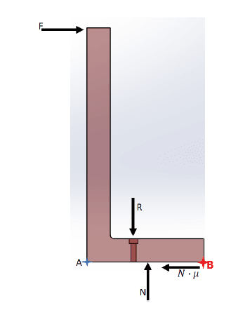
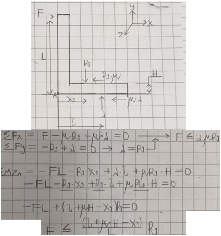
I am trying to figure out what's wrong with a free body diagram I wrote down.
I added a pdf file with a description of the problem.

please give your advice

Thanks
 
Replies continue below

Recommended for you

no attachment !

another day in paradise, or is paradise one day closer ?
 
You are assuming your normal force N occurs at a single point in the middle of the bracket which is not realistic.

If you are trying to calculate "R" based on a given position of the screw and a given force "F" you will be much better off by doing a sum of moments around the point B I added below.

If you are actually minimizing the bolt preload "R" to the point where it just balances out with force "F" then your normal force "N" will drop to zero everywhere except at point B. You are then free to neglect it when summing the moments about point B.

Untitled_yogphj.png
 
See my attachment (if I remember !?) …

the first pic shows the free body of the angle … the applied force is reacted by shear in the fastener and a couple on the base … tension in the bolt and a compression distributed force (these are prying loads).

the second pic shows preload. Preload really complicates a simple angle. the preload in the bolt is reacted by a compression field around the bolt (with the same centroid). As this reacts the applied load the preload in the bolt relaxes as the compression field moves towards the toe of the flange (closer to point B).

What's the minimum preload ? zero, if you can accept some small gapping of the heel of the angle (point A).

What's the practical minimum ? well, determine by test … have no preload, apply the load (and the heel lifts); then torque the bolt to close this gap. But there'll be variability in service ...

another day in paradise, or is paradise one day closer ?
 
 https://files.engineering.com/getfile.aspx?folder=59252e1c-a3c4-43af-b18d-bed6c072556d&file=Doc22.pdf
hello and thanks for replying.
I am sorry, but I think I wasn't clear enough -
I am going to fasten the bolt in the same torque regardlessly, while my aim is maximizing the allowed F by deciding where the bolt is.
I have some questions regarding your answers.

Dear "hendersdc"
I put an equivalent force "N" in the middle, while the assumption that I have a uniform distributed load along the bottom (though uniform isn't really correct). I use an equivalent force for easing the calculation of the reaction.
You said I better do a sum of moments around the point B, but in statics it doesn't matter to which point I take as a reference.
Each reference point in the space should give me the same result, and it doesn't happen here.
I couldn't understand the claim that "N" will drop to zero everywhere except at point B...as long as you have a preloaded screw - you have a normal force reaction by the lower surface (floor).

Dear "rb1957"
your first diagram is the quite the same as mine besides the reaction locations along the base.
in this case, how would you calculate equilibrium? you didn't say if there is any problem with my equilibrium equations [dazed].
please look at my statement above (I am going to fasten the bolt in the same torque regardlessly, while my aim is maximizing the allowed F by deciding where the bolt is) so zero preload doesn't exist.
 
the in-plane reaction to F is F sheared on the fastener (as hydtools above), rather than a friction reaction.
"N" wouldn't be a point reaction (though maybe you've drawn the point summation of a distributed force ?).
You aren't showing prying the way I'm used to seeing it (the way I drew it).
Equilibrium is simply the in-plane force equals the applied force,F; the out-of-plane forces are a couple, reacting the overturning moment.
Including preload in this type of bracket makes the solution much more complex, possibly beyond any normal hand calc.

The "best" location for the bolt is as close to the vertical leg of the angle as possible. If the horizontal leg isn't stiff enough for the distributed prying force, it'll develop a plastic hinge.

another day in paradise, or is paradise one day closer ?
 
If you are using any point in space you see two couples. F x L , where L is the distance between F and mu*N. R x X, where X is the distance between R and N.
F=mu*N
R=N
If you are predetermining R as in always setting the same preload, then R can not depend on x. X will determine value of F to equal the preload. At that point, friction becomes zero.

Ted
 
Thanks for your help
what actually helped me was the understanding that I omitted the force under the bolt head (actually a friction as well).
55555555555_jb302n.jpg
 
You're assuming N stays where it's at when x varies. Put N under the bolt and move it with the bolt. The bolt force, R, then increases as you move to the right.
 
1) fastener shear is not normally friction (mu*Normal force). It is what it need to be (being reacted by the bolt).
2) I think the fastener shear is on the parting plane on the angle (not under the head).
3) the fastener shear = F
4) why use such an odd symbol for the normal reaction on the angle leg (what looks like 1/2 a sqrt sign) ?
5) have you lost interest in fastener preload ? good
6) fastener tension (P) equals the other normal force (N), separated by a distance d
7) P*d = F*L
8) what is a reasonable value for "d" ? 2/3 of the distance from the fastener to the tip of the angle.

another day in paradise, or is paradise one day closer ?
 
Since the friction force is independent of surface area the normal force should be coaxial to the bolt preload and not assumed to be distributed over the length of the bolted leg. There would be no distance between P and N.

Ted
 
No Ted, I think "N" is the other 1/2 of the prying reaction. (P and N are the couple reacting F*L).

another day in paradise, or is paradise one day closer ?
 
rb1957,
Go back to the first illustration and description. N is defined as the normal force used to calculate the force of friction.

Ted
 
hey everyone,

I have to say that I am quite confused [sad] and not sure about the right solution since there were some different answers.
For example, claiming that shear force by the bolt exists maybe is a possible case, but the design intention is that the friction itself will prevent enough resistance so the bolt thread won't touch the through hole in the plate.
In addition, some say the N (normal force reaction by the plate) should soincide with the bolt axis, and some didn't say it.
 
"For example, claiming that shear force by the bolt exists maybe is a possible case, but the design intention is that the friction itself will prevent enough resistance so the bolt thread won't touch the through hole in the plate." … then you should have expressed this design intention.

so then it is simply …
friction reacts the applied load … F = mu*N, N = F/mu
and the couple reacts the overturning moment F*L = N*d, d = L*mu
where d is the distance between the bolt axis and the CP of "N"

so then the question is … what is the distribution of "N" ? … triangular (from bolt CL to free edge) would be a reasonable assumption.

another day in paradise, or is paradise one day closer ?
 
Status
Not open for further replies.

Part and Inventory Search

Sponsor