Continue to Site

Eng-Tips is the largest engineering community on the Internet

Intelligent Work Forums for Engineering Professionals

  • Congratulations pierreick on being selected by the Eng-Tips community for having the most helpful posts in the forums last week. Way to Go!

Problem with plastic deformation (Plateau) in 2D model 3

Status
Not open for further replies.

Algirdas13

Mechanical
May 27, 2023
36
Hey everyone,

I'm facing a problem with non-linear analysis using shell elements. The software is Nastran in CAD (Autodesk Inventor Add-in).
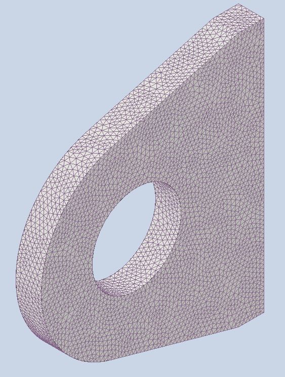
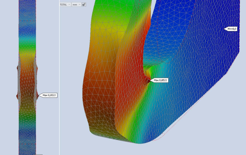
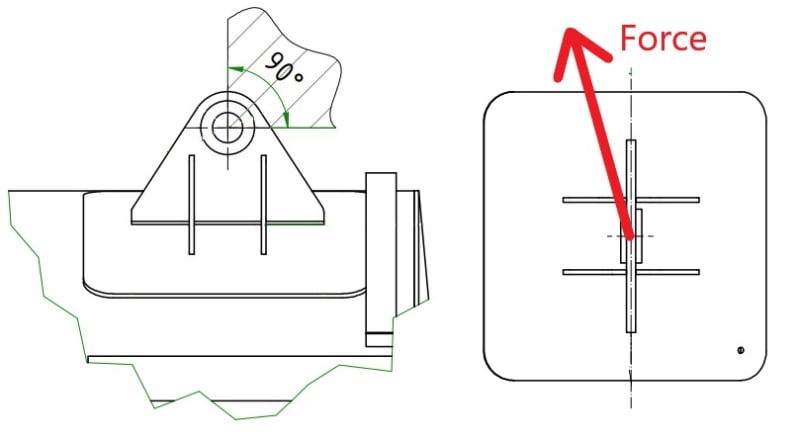
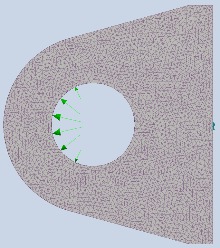
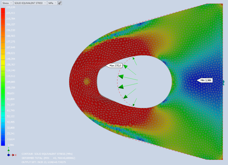
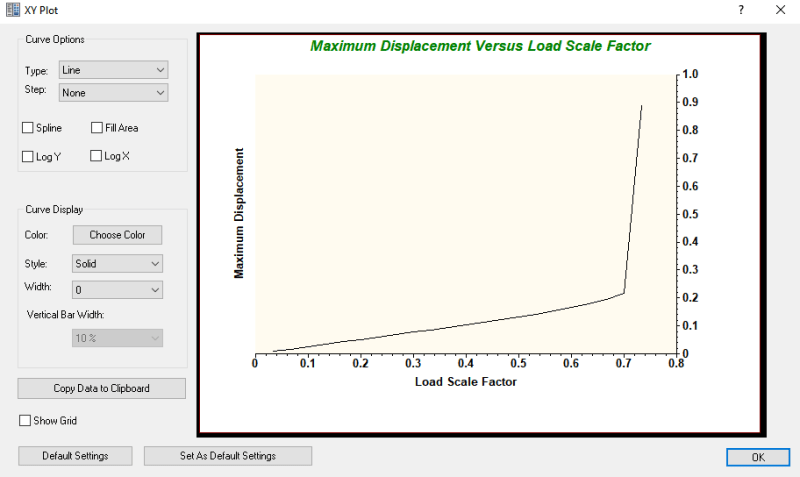
I did a simple analysis of the lifting lug by using 3D solid elements (parabolic order) and bi-linear material (LGDISP is on). The model performed pretty well and managed to reach the plateau (plastic deformation).
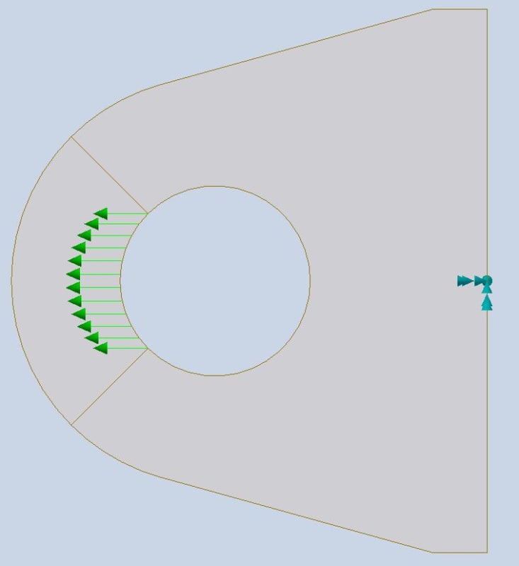
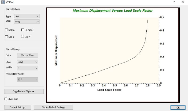
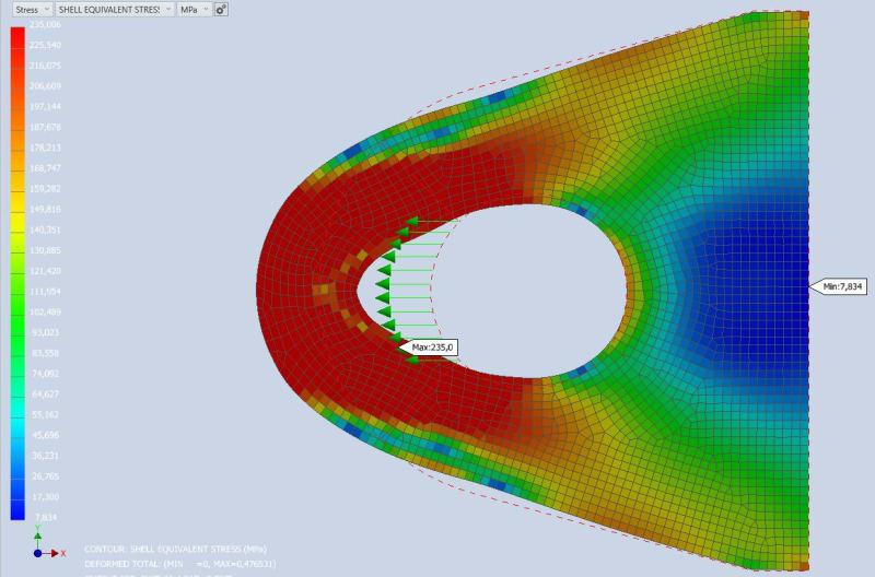
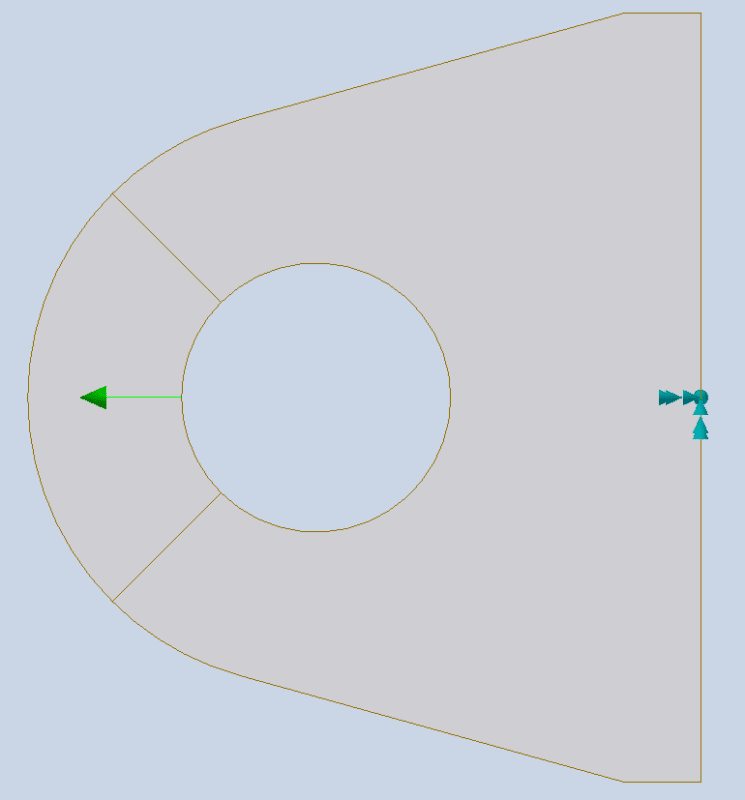
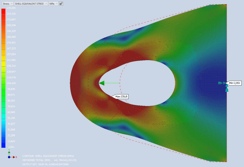
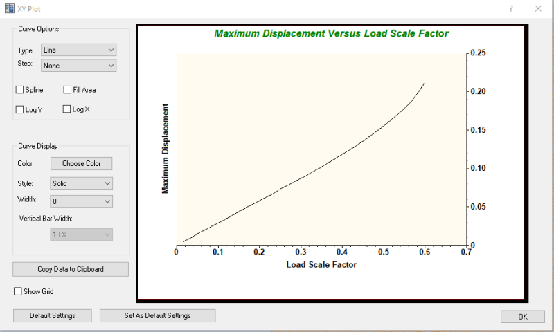
After that I tried to do the exactly same simulation but using 2D shell elements (parabolic order), bi-linear material (LGDISP is on). In such case during the analysis a plateau (plastic deformation) wasn't reached. Solver managed only capture the elastic-plastic transition and then stopped because of calculations resulting in divergency.

For both analysis I used same parameters, material properties and force. For 2D calculation I also tried to increase number of increments.
Maybe someone could help me out to figure out or share some insights what I did wrong in analysis where I used shell elements?

P.S. these calculations are not meant to determine capacity of lifting lug but rather to learn how to perform a non-linear analysis and see the correlation regarding the hand calculations.

Shell setup:

2D_boundary_conditions_vqwtxd.png

2D_calculation_results_elngau.png

2D_calculation_load_scale_and_max_disp_phhbt7.png


Solid setup:

3D_boundary_conditions_kocxvg.png

3D_calculation_results_pxe3ch.png

3D_calculation_load_scale_and_max_disp_htgddm.png
 
Replies continue below

Recommended for you

Isn't the load applied differently in both cases or are those equivalent load definitions ? The top on looks more like a uniform force and the bottom one like bearing load distribution.

Also, by 2D shell elements do you mean plane stress/strain analysis where elements have only 2 translational DOFs or full shell elements with 5 or 6 DOFs ?
 
The shell result looks more believable to me, the sudden transition in stiffness in the solids one is not how real structures work.

Cheers

Greg Locock


New here? Try reading these, they might help FAQ731-376
 
As already har been said, the load is probably not applied in the same way. It looks like a more concentrated load for the shell model.

The software is what used to be called NEiNastran so I don't think the problem is the solver. However, how you apply load using Inventor is probably something you need to investigate.
 
Yes, the loading appears different in the two cases.
And, the loading in both cases is Wrong for a pin loading the hole. It would be better to apply a displacement to the hole edge matching a pin shape.
 
TLDR ...

I too thought about loading.
SWC's idea ... model the pin, load the pin, contact with the hole bore, large displacements, non-linear material (which I think you have already).

The #D solid model has several elements thru the thickness, yes? so this is different to the 2D shell model.

IMHO, all this'll "prove" is that maybe FEM predict details like this well, compared to tests, but the details to model are "bizarre", for starters the dependence of precise bolt clearance in the hole;
and that our hand calcs are very conservative.

"Hoffen wir mal, dass alles gut geht !"
General Paulus, Nov 1942, outside Stalingrad after the launch of Operation Uranus.
 
Hey guys!

This is a full shell model with 6 DOFs. The picture that I uploaded regarding the applied load wasn't accurate. The density of load arrow representation was low, for this reason representation of load appeared like single arrow. Please find below the accurate representation of applied load.

The loads in shell and solid models differs. In the solid model I used the bearing load. In the shell model I used simple load, but crated the split so there would be an area (curve) on only which load is applied. I did another nonlinear analysis using shell model, the load was applied in different way. In such case solver managed to reach the convergence and plastic deformation (plateau) was reached. For this reason, I also believe that there is a problem with the way of applied load rather than with solver.

Capture_xyq0wo.jpg
 
Hi once again,

I just wanted to let to know that within the shell model there was reached quite similar results to the solid model that I'm happy enough. The changes that I did was increasement of the numbers of increments and bisections.

In the solid model the capacity of lug was reached around 239 kN. In the shell model the value was 245 kN. In the hand calculations taking into account worst case scenario for the shear of the lug, the capacity was 217 kN.

Load_scale_oxjjm5.jpg


Stress_field_lkwnhg.jpg
 
the big difference (AFAICS) was the 3D model had a markedly different stiffness curve, almost a brittle behaviour

"Hoffen wir mal, dass alles gut geht !"
General Paulus, Nov 1942, outside Stalingrad after the launch of Operation Uranus.
 
rb1957,

I do agree that in solid model the curve looks quite off and it really does look more like brittle material behavior. I believe that this could be because of two factors.
The first one is the number of the increments. The solid model had less increments compared to the shell model.
The second one is probably because in solid model I used the value of the load 350 kN while in shell model I used 300 kN. That probably could had the impact on the scale of the curve. For this reason probably the shell model captured the curve in the elastic-plastic zone more clearly and visible.
 
I suspect a significant difference between the models is that the 3D model had several elements through the thickness.

I suspect too that you "messed" with the element formulation in that it looks like the surface of the shell is smaller (or at least of the same scale) as the thickness. This is probably "not good".

But when you say you're satisified with the two models, could you show the stiffness curve of the 3D element model ? did it "flatten out" like the shell model, or was there still the very sudden transition ?

I wonder what your material curve looks like ?

"Hoffen wir mal, dass alles gut geht !"
General Paulus, Nov 1942, outside Stalingrad after the launch of Operation Uranus.
 
rb1957,

I believe there is enough elements through the thickness. Please see the picture below.

I'm sorry, but I don't fully understand what you meant to say by "I suspect too that you "messed" with the element formulation in that it looks like the surface of the shell is smaller (or at least of the same scale) as the thickness. This is probably "not good"." Could you please explain a little bit what you meant by saying that? I would really appreciate that because it seems like an important thing that I'm not familiar with.

For the analysis I used elastoplastic material model (bi-linear material without a slope, completely flat line, after reaching the yielding point). In this case yield point is 235 MPa, after that completely plastic strain without any isotropic or kinematic hardening.

I did a little investigation of the results. I believe that the displacement results are effect at one point (sudden jump in displacement) because the pressure resistance (bearing resistance) starts to kick in. In such case some elements deforms not only parallel to the load, but also to the sides of the lug through the thickness. And I believe this is at least a one of the differences with shell model. Please see the picture below.

Elements_t7voft.jpg
bearing_il0gcp.jpg
 
The deformation results are still completely wrong for a pin loaded lug.
 
Hi SWComposites,

I agree that the deformation results are way off comparing it to the actual pin loaded lug. However, I'm wondering maybe this is still acceptable having in mind that these calculations are only meant to approximately determine lug capacity due to lug shear failure?

Also, one of the reason why I was interested in such calculations was that I'm not able to manage to find clear information how to calculate (by hand) lug capacity when lug is loaded by combination of normal force and bending. Perhaps you have any recommendations or insights how to perform such hand calculations?

To capture nearly right results of deformation I should model pin and contact between pin and lug. Having in mind that this should be done in Nonlinear analysis, that would be way too time consuming and way too complex for such task. This is a reason why I'm trying to find an cheap way of getting only approximately results of such case for an early stages of the design.
 
Do a google search for “air force lug analysis” and lots of useful info will come up.

By “bending” how exactly is the moment applied? By pin bending and non uniform contact thru the thickness?

Are you designing a specific lug? For what application?

And by shear failure, do you mean shear along lines tangent to the hole aligned with the loading direction? And note there are several other lug failure modes that must be checked.

As for modelling the pin, if you don’t want the headache of contact elements, then apply a enforced displacement field to the hole surface and extract the reaction force. If you want, check the forces at the enforced displacement nodes, release any that are in tension, and rerun. (Poor man’s contact modelling).

 
Hi Algirdas13,

Would you mind sharing you .ipt files for this item? I use Nastran InCAD.
 
SWComposites,

At the moment I'm not designing any specific lug. Nevertheless, in near future I will design some lifting lugs and lugs for hydraulic cylinder mounting.

Please find attached picture regarding the bending moment. Basically there will be some lifting lugs that will experience not only radial forces but also some amount of axial forces because of force applied in angle.

By shear failure I mean "Double shear failure".

That's some really good advice, I was unfamiliar with such approach (enforced displacement and then rerun by releasing elements that are in tension). Seems really useful, I will try it out. Thanks a lot, it's a pleasure to learn such stuff here from engineers like you!

Lifting_Force_hgorf3.jpg
 
As long as the force is applied on the pin and close to the hole (the only sensible way to design this kind of structure), the failure will be due to bolt shear and bolt bearing against the plate. A simple method would the be to take the resultant of the force, apply standard formulas (e.g., AISC or eurocode) for shear of a bolt (pin) and bearing against the plate, and be done with it.

Using an ideally plastic material model without hardening is already a large source of uncertainty in what seems at first glance to be an "advanced" calculation, so unless you go "all the way" (and do some tests) to perhaps optimize weight of 1 000 000 of these pins, the effort does not seem worth it.
 
or lug shear...

-----*****-----
So strange to see the singularity approaching while the entire planet is rapidly turning into a hellscape. -John Coates

-Dik
 
Status
Not open for further replies.

Part and Inventory Search

Sponsor