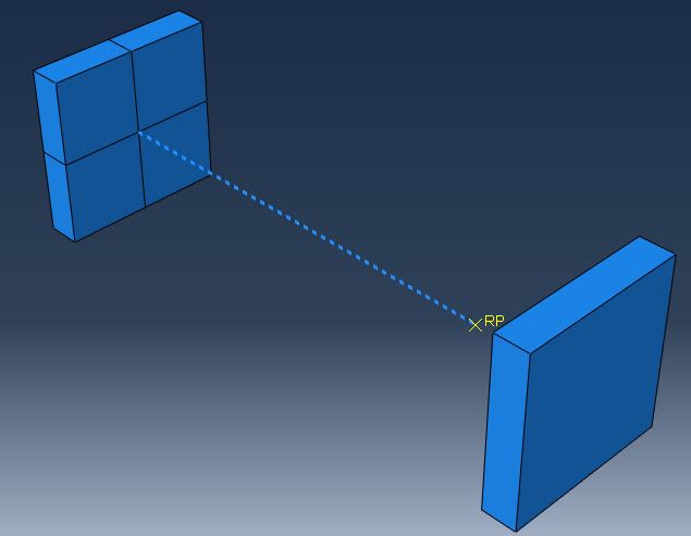
Hi everyone, new here and I hope this isn't the same question over and over again, sorry in advance.
I'm having problems with connectors, specifically finding one meeting my needs: I need to model nails with a connector having three different elastic-plastic behavior in the three different directions U1, U2, and U3; I'm not interested in UR. I tried CARTESIAN first, then BUSHING, but I always obtain the same result: when I move the ending point of the connector in the direction the connector develops, let’s say X, I obtain results similar (not exactly the same, and this is another problem) to those I expect, when I do it in Y or Z, I obtain something around zero (10^-9). When I apply the displacement in y, I see in the visualization that the orientation system of the connector, placed in the first point of the connector, rotates at each step of the analysis around the Y axis of about something more than 180° (?).
The first point belongs to a 3D plate with encasters and the second is a reference point constrained to the surface of another 3D plate. The displacement is applied to this second plate.. I also tried with a two point wire alone, same result.
I also get this warning for the first point of the wire, the one belonging the 3D plate: Solver problem. Zero pivot when processing D.O.F. 4 of 1 nodes. The nodes have been identified in node set WarnNodeSolvProbZeroPiv_4_1_1_1_1. I get this multiple times, for DOF 5 and 6 too.
When I apply a displacement in 2 and 3 I get the first warning way more times and I also get this: There is zero FORCE everywhere in the model based on the default criterion. please check the value of the average FORCE during the current iteration to verify that the FORCE is small enough to be treated as zero. if not, please use the solution controls to reset the criterion for zero FORCE.
It is evident I’m doing something wrong, but I don’t know what. I hope someone could help me. Thank you very much.

