Burunduk
Mechanical
- May 2, 2019
- 2,476
What would be your preferred way of manually inspecting this profile tolerance?

Follow along with the video below to see how to install our site as a web app on your home screen.
Note: This feature may not be available in some browsers.
Got it.pmarc,
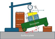
I merely illustrated mfgenggear's suggestion as I understood it. I think yes, with the dimensions of the sine bar and the exact and constant placement of the pair of V blocks taken into consideration, it will be necessary to calculate trigonometrically the vertical height from the surface plate to the intersection point of datum axis A (center of the pair of V blocks) and datum plane B (the inclined top face of the sine bar). Can't tell the exact math right away, I'd probably check that with CAD. To that, I would add 35cos15° to know the height of the zero reference stack of gage blocks.
")
All I wanted to accomplish with my question was to hear that an optimization would be needed as an additional step in the inspection process to ensure satisfactory level of confidence of readings.pmarc, that's why I said "unless I'm missing something critical"
But speaking seriously, I think that the unconstrained degree of freedom makes it OK to optimize the rotation of the part around the datum axis for having the "best-fit" to a horizontal condition. Although on second thought, it would be an optimization not just for horizontality but also for the location relative to the zero - a bit of a compromise of each for minimizing the measured value. Anyhow, I think it should be OK. Do you agree?
My additional question was not about the manufacturing precision and the accuracy of gage components used in the proposed setup. Notice that in my example I made the flat surface perfect, yet the dial indicator reading could get quite significant due to a non-optimal installation of the part before taking the readings.pmarc
if the correct angle is used on the sin plate.
and sliding the dial indicator to cause the
dial indicator over the profile of the part.
the dial indicator should not move more than
.050 wide. if it is ground it will be .0005 inch..
to grind the parts the same setup would be used to grind the surface after A and B are
trued up. all degrees of freedom would be restraint.