Eng-Tips is the largest engineering community on the Internet

Intelligent Work Forums for Engineering Professionals

Profile Of a Line application 2

Status
Not open for further replies.

CTengIS

Mechanical
Jul 25, 2023
30
0
0
IL
profile_of_line_rect_section_g0esdl.jpg


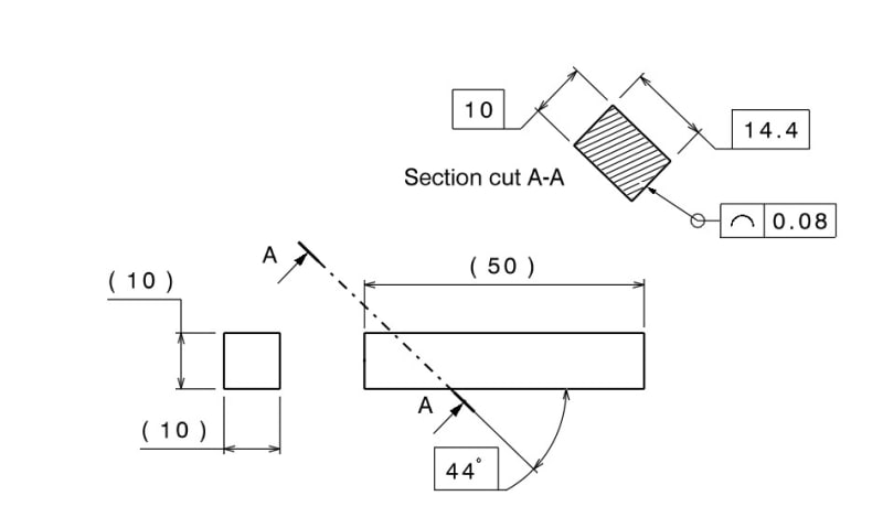
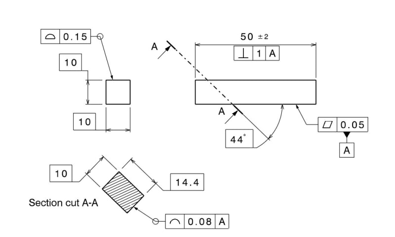
Hi, I would like your advice weather this application of profile of a line is valid according to ASME Y14.5.
In case you are wondering what this is for, I have a pile of square 10X10 mm stock bars that I want to later be cut to slices at that angle and get the 10X14.4 mm dimensions accurate within 0.08 mm all around. I'm fine with the angled edges that will result in the periphery. I'm not sure how accurate the bars are and I want them sorted according to this profile requirement. I know I can just calculate the required tolerance on the 10 mm square cross section but I want to try this method anyway. So please comment on weather this is valid per the standard. Thanks.
 
Replies continue below

Recommended for you

I guess it is valid but might not be enough for a full definition. In general profile of a line is used as a refinement of a surface profile.
 
Thanks greenimi for answering.
I get what you say about full definition and profile surface refinement.
See the new dwg below. Would you now say it's fully defined and valid without any doubt? Notice that for the line profile I also added a reference to datum A to provide robust orientation to the tolerance zone.

profile_of_line_rect_section-fully_defined_uneuj1.jpg


Just to clarify - suppose that the face that is found to be flat enough to be used as datum feature A is marked, both for the inspection of this and for use in next machining operation.
 
The problem with the first drawing is that it cries out for a datum reference, especially since a basic angle is being used.
For your second drawing, I'm not really sure... it's a very busy drawing (GD&T-wise) for such a simple part.
 
Garland23,
I understand your point about the first drawing, and I agree.
As for the second drawing being busy, well that's my take on "full definition".
I guess I could lighten it up a bit stripping it from some GD&T if I replace the all around surface profile on the square shape making the 10 mm dimensions plus and minus, but I think it would not simplify the situation as it would imply rule #1 which is not needed here because those faces don't mate in a slot. And also, another perpendicularity tolerance would be needed for "full definition".

Anyway, I'm mainly concerened with the profile of a line validity as applied at that basic angle, considering ASME Y14.5 definitions.
 
The second drawing is much better defined.
You are basically asking whether you can define a true profile for a profile of a line in an untrue view of the toleranced feature.
I don't see a strong indication against it in Y14.5, but it may be debatable.
 
CTengIS said:
Would you now say it's fully defined and valid without any doubt?

Is your drawing just for illustrative purposes or is this the one you intend to use?
I ask because it seems like you could have a bar that passes the initial inspection of 10x10 with a .15 profile, but would fail the inspection after being cut. If I'm reading this correctly, you could have a bar come in at max material condition 10.15 x 10.15 which would pass the .15 profile; after being cut, the bar is still 10.15 wide, which would fail the .08 profile tolerance (max width of 10.08).
 
cowski, you are right, it doesn't seem right. But would it be OK if instead I had two dimensions of 10+/-0.15, and profile of a line as shown kept, as a refinement of directly toleranced dimensions?
 
My post above assumes that you are making a single cut to the stock bars. If there is another operation that changes the width of the bar, ignore my comments.
 
No, you're correct, and I now think the surface profile + line profile combo was overkill. Your comment was helpful. But would the line profile defined at angled cross sections make sense when used as a refinement of 2X 10+/-0.15 ?
 
Status
Not open for further replies.
Back
Top