Continue to Site

Eng-Tips is the largest engineering community on the Internet

Intelligent Work Forums for Engineering Professionals

  • Congratulations MintJulep on being selected by the Eng-Tips community for having the most helpful posts in the forums last week. Way to Go!

Profile of contour

AMontembeault

Mechanical
May 13, 2014
29
I have a cylinder (actually a "pipe"), from which I establish datum "A" as the axis of the OD of the cylinder, datum B as an end of the cylinder, and datum C from a hole drilled into the side of the cylinder.

On the OD of the cylinder, I have to machine a grooved contour, one that presents itself as a projected rectangle or circle along its perimeter, and as a semi-circle (non-FOS) in any cross section. Below is a quick and dirty example of what I'm trying to describe, with the contour highlighted (numbers are just made up and do not necessarily reflect what we're really dealing with).
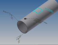
Contour.jpg

Initially, these contours were controlled by surface profile with respect to datums A|B|C. The problem is, we really want the depth of these contours set from the OD surface, because there is a considerable, unavoidable tolerance on the OD of the cylinder, and we're running into CMM issues when inspecting these contours with respect to datum axis A.

Is a directly toleranced dimension on depth unavoidable? if so, how would I go about controlling the other parameters of the contour? I'm not sure the overall perimeter meets the definition of a FOS (at least, not radially), and I know the groove cross section isn't a FOS, so my gut feels that using positional tolerance seems iffy. Im curious to know how others would approach this.
 
Replies continue below

Recommended for you

What you appear to be asking for is for the profile to change as the diameter changes. Is that correct?

Like if the OD doubled in diameter then the centerline length of the slot would be the same, just the curves on the ends would unwrap to a larger radius match the larger OD?
 
What you appear to be asking for is for the profile to change as the diameter changes. Is that correct?

Like if the OD doubled in diameter then the centerline length of the slot would be the same, just the curves on the ends would unwrap to a larger radius match the larger OD?
Hm, sort of. I want the depth of my groove to shift with the change in diameter, rather than fixing it to the axis of the cylinder.
 
Do you want the angle to stay the same or the perimeter to stay the same as the radius of the groove change?

Accommodating the change in diameter is either a sort of scaling or transformation problem which Y14.5 is certainly not designed to deal with. You need to specify whether the groove carves a longer path on a larger radius or carves the same length path and goes around less angle on the larger radius.

The problem is that Profile of surface, like most other Geometric Characteristic tolerance controls, envisions a certain rigidity from which deviations are measured. This is adding a linear (radial) variation that is not rigid.

There isn't an "unproject" or "unwrap" function in ASME Y14.5.
 
Hi, AMontembeault:

You can control it with a local depth dimension as depth of blind holes is considered feature of size. What is function of this groove? What does the mating part look like? Is it a cavity to maintain lubricant?

I assume that you use a CNC milling machine with a ball end mill. You know that your CNC machine has no knowledge of cylindricity of your pipe. So, it is not reasonable to expect precision depth without controlling accuracy of your pipe. It also depends on how the pipe is chucked on your machine.

If you really want a precise depth, you could use a sinker EDM. But it won't be economical.

Best regards,

Alex
 
OP
My opinion dim from center line of datum -A-
The od needs to be machined for tooling.
Regardless of od change , the pocket will not be effected by the cylinder od
 
AMontembeault,

Beware -- six inch pipe has an OD of 6.625in.

In your case, you need a section view of your groove, showing the depth of the slot from the outside face, with a +/- tolerance. This specifies what you want.
 
The theory of "feature of size" in ASME Y14.5 is based on stability or robustness of features. Depth of a blinded hole is stable and robust in math and should be consider feature size even though there are no physical opposing elements. It is debatable, but depth of a groove should be considered "feature of size".
 
The problem is, we really want the depth of these contours set from the OD surface, because there is a considerable, unavoidable tolerance on the OD of the cylinder
That is indeed a problem.
Whatever you do datum-referencing the cylinder will give you its axis as a reference.
 
Last edited:
The theory of "feature of size" in ASME Y14.5 is based on stability or robustness of features. Depth of a blinded hole is stable and robust in math and should be consider feature size even though there are no physical opposing elements. It is debatable, but depth of a groove should be considered "feature of size".
Not that rubust if you consider that the face in which the hole was made and the other end of the cylindrical portion of the hole are truly parallel only in theory. Then also the form error of the face will add even more ambiguity to the depth evaluation.
 
The problem is, we really want the depth of these contours set from the OD surface, because there is a considerable, unavoidable tolerance on the OD of the cylinder, and we're running into CMM issues when inspecting these contours with respect to datum axis A.

Is a directly toleranced dimension on depth unavoidable? if so, how would I go about controlling the other parameters of the contour? I'm not sure the overall perimeter meets the definition of a FOS (at least, not radially), and I know the groove cross section isn't a FOS, so my gut feels that using positional tolerance seems iffy. Im curious to know how others would approach this.
You may still use regular profile to A|B|C as you have it with the true profile fully defined with basic dimensions (explicit or derived from CAD model) but also put a directly toleranced dimension as a refinement for the depth.

Today, the standard does not provide a robust interpretation for depth dimensions like this anyway, so I don't think you will make things any worse.
 
Last edited:
actually the faces and the od need to be machined square, and faces parallel.
then these surfaces can be used as datum and tooling surfaces. making the other attributes more precise.
 
You may still use regular profile to A|B|C as you have it with the true profile fully defined with basic dimensions (explicit or derived from CAD model) but also put a directly toleranced dimension as a refinement for the depth.

Today, the standard does not provide a robust interpretation for depth dimensions like this anyway, so I don't think you will not make things any worse.
pmarc,
I agree and think that your suggestion is totally valid. Each of the requirements would need to be met or the part is rejected.
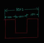
But what would you answer to a person, who would claim that since the combination of profile and toleranced diameter indirectly limits the depth, it is "overdimensioned". Saying it's like the idea of both chain-dimensioning with all tolerances specified and giving a toleranced total length in the example here. You can't meet the 30+/-2 requirement if you make enough use of the other tolerances, that's true.

1000017262.jpg

I have come across people (usually used to mainly coordinate tolerancing) applying this logic to geometric tolerancing and "refinements". I intuitevely disagree with them, but am unsure how to counter their arguments.
 
You may still use regular profile to A|B|C as you have it with the true profile fully defined with basic dimensions (explicit or derived from CAD model) but also put a directly toleranced dimension as a refinement for the depth.
Hmm, how do you know this will be interpreted as a refinement?
You know the UOS is my pet peeve. I even heard that Y14.5 (when Paul Drake was chair) tried to put UOS - and its messy definition-- on the agenda. I hope did not fell thru the cracks.

So, back to the refinement, the current profile is for the sides (all around including radii) of the opening and the depth is for the bottom, right? Then why it is refinement?
If another profile is (in addition to the all around applied on the sides +radii) added to the bottom feature THEN the plus -minus-your directly toleranced dimension- COULD be considered refinement?

Maybe I am missing something....and I know you pmarc could straightened me out.
 
The groove radius needs to be basic, the path needs to be basic. The reference for the location of the path is the axis that is independent of the radius of the pipe.

If the local depth of the groove is what is to be controlled then the path cannot be basic based on the axis; it needs to vary as the OD of the tube varies.

Since the CNC is apparently not capable of adapting to the outside diameter variation, and the kind of allowed variation is not specified, none of that works.

ASME Y14.5 doesn't have the notion of a variable surface as a datum feature - just the geometry derived from that surface. In this case, that is an axis.

Four descriptions are available.

One is: The path for the groove is given a parallel projection from a 2D profile onto the actual surface.
Second is: The path is wrapped like a decal or a sticker from a 2D profile onto the actual surface.
Third is: The path for the groove is given a parallel projection onto an ideal surface, but that projection is then projected radially onto the actual surface
Fourth is: The path for the groove is wrapped like a decal or a sticker onto an ideal surface, but that is then projected radially onto the actual surface.

The first two tend to maintain a fit with parts that conform to the surface - like a raised part that engages the entire groove simultaneous.
The second tend to maintain the angular relationship for motion relative to another part - like a cam follower that engages only part of the groove, but transfers the angular constraint.

None of these are supported by ASME Y14.5
 
Hmm, how do you know this will be interpreted as a refinement
There is no exact definition in ASME Y14.5 of a "refinement".
An obvious refinement is: " hey, that profile of a surface limits form, location and orientation at the same time within 0.5 mm, but I will add this parallelism requirement to make sure the orientation error does not exceed 0.1 mm. "
A less obvious refinement, as I think pmarc means, is " hey, those profile and size tolerances control the size and form of the OD and the form, location, and orientation of the groove, and indirectly the depth - but I will add this directly toleranced dimension to make sure the depth is controlled tighter " - I think this can pass as a refinement too.
 
Last edited:
There is no exact definition in ASME Y14.5 of a "refinement".
An obvious refinement is: " hey, that profile of a surface limits form, location and orientation at the same time within 0.5 mm, but I will add this parallelism requirement to make sure the orientation error does not exceed 0.1 mm. "
A less obvious refinement, as I think pmarc means, is " hey, those profile and size tolerances control the size and form of the OD and the form, location, and orientation of the groove, and indirectly the depth - but I will add this directly toleranced dimension to make sure the depth is controlled tighter " - I think this can pass as a refinement too.

OK. So a stand alone depth profile (not a general profile) should be applied to the bottom of the opening, right?

Burunduk,
This is what you are saying? Because, if general profile is to be applied, then I think it is not crystal clear.
But if you apply a stand alone profile to the bottom of the opening AND in addition you apply what pmarc reccomended (a direct toleranced dimension) then I think you have a strong argument that BOTH requirements/ specifications shall be meet.

Is my understanding correct?
 
Last edited:
how it is dimensioned is Meaningless if the part cannot be realistic obtained without the proper machined restraints. some how the propher tooling requirements get lost in the deciphering of the specification.
back to basics 101 machining practices and less arguing what is the dimensioning.
 
greenimi,
Burunduk nailed it.

Burunduk,
I guess that person might or might not be right depending on the tolerance values used.

In the OP's case, I assume the profile tolerance must be more generous than the tolerance for the groove depth, hence, in my mind, my proposal makes sense. But if the overall tolerance for the depth was to be greater than the depth variation calculated from the stack-up of tolerances (for the OD size and the groove profile), then specifying the depth dimension would not work.

The same story with your sketch. What you currently show makes sense to me, but if the tolerance for the 30 dimension was changed to, for example, +/-5 then that dimension wouldn't look right.

A side note: There is a figure in the Y14.8 standard for cast, forged, and injection molded parts that shows a sort of similar scenario to yours; a wall of nominal thickness of 4, for which both sides are controlled with a general surface profile tolerance of 0.8 relative to a fully constrained DRF, but there is an additional directly toleranced wall thickness dimension of tolerance +/-0.2 added to that. In my opinion, since the size limits for the wall thickness are within the limits otherwise imposed by the profile tolerances (i.e., +/-0.8), everything holds water.
 

Part and Inventory Search

Sponsor