Eng-Tips is the largest engineering community on the Internet

Intelligent Work Forums for Engineering Professionals

Profile of surface combined with dimension tolerancing

Status
Not open for further replies.

Wuzhee

Automotive
Jul 12, 2022
269
0
0
DE
Hello everyone,

I'm overwhelmed by the amount of information regarding GD&T profile and I can't seem to find my answer here (or I got exhausted trying to understand all the information)
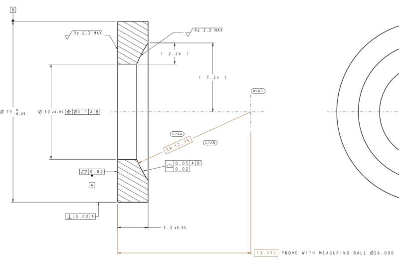
We have a small part with a sphere surface.
Based on ASME Y14.5-2018 is this dimensioning correct?
I'm currently modeling an assembly with parts at MMC to check for intersections and functionality. But when I looked at this drawing I got confused how to calculate the maximum material condition. (i.e. smallest sphere size)
Is it true when the sphere surface is at it's minimum size, the form has to be perfectly spherical, which is impossible to achieve?
Does the 0.05 profile refine the size tolerance? For me, it's confusing because if I go down in size, for e.g. at 12.92 I could no longer have a 0.05 profile tolerance.

Would it be reasonable to control the size, location and form with only the surface callout and basic dimensions?
Like |profile|0.05|A|B| and |SR13| and theoretical shpere center |14| are basic.
profile_wnlao5.png
 
Replies continue below

Recommended for you

Wuzhee,

How are you going to measure and inspect SR13+0/-0.1?

Given that your profile tolerance is 0.05, it will be violated by any dimension error greater than [±]0.025. Your profile tolerance is a composite that accounts for position as well as the form dimension.

Make your spherical radius tolerance basic, and inspect the profile with a fixture and shims.

--
JHG
 
The profile tolerance is controlling that spherical surface thus the spherical radius has to be basic since a true profile has to be defined by basic dimensions. The radius is NOT a size dimension so this isn't a refinement of a size dimension. This specification is incorrect. The radius must be basic.

John Acosta, GDTP Senior Level
 
Drawoh, after release we measured with CMM, and during prototyping we "measured" with ink coloring (if there's no ink, there's no contact with the ball).

In my understanding both the sphere radius and center of sphere has to be basic, am I right? So we can say that as per ASME Y14.5-2018 this is incorrect. (our TB points to our company standard which obliges Y14.5-2018 be applied to every drawing).

My main concern was that I couldn't find an unambiguous definition that profile dimensions MUST be basic. Only a recommendation on some gd&t sites that one should use basic and avoid dimension tolerancing when applying profile gdt.

Wuzhee said:
Like |profile|0.05|A|B| and |SR13| and theoretical shpere center |14| are basic.
So is that correct? both dimensions are basic and profile controls size, location and form.
 
Wuzhee... yes, basic dims are required per ASME Y14.5-2018. Paragraph 11.2 states that a profile tolerance defines a tolerance zone to control qualities "relative to a true profile." And according to paragraph 3.68, a true profile is defined by basic dims (or math data, CAD model, etc.).

John-Paul Belanger
Certified Sr. GD&T Professional
Geometric Learning Systems
 
@Belanger,

Thanks for clarifying. In the meantime I read through at least a dozen topics here and several pages of your blog finding answers and explanations.
My only regret is there are many references to paragraphs, figures, pages here on the forum and elsewhere on the internet but without pictures/screenshots. And as a visual person myself, I'm really addicted to drawings and pictures. After all, drawings are the universal language of engineers.

And my company standard requires ASME Y14.5-2018 but we can't look into the standard to which we have to comply. And they are against gd&t training because of cost-cutting reasons. Very sad.
 
Luckily, I was able to find a pdf of Y14.5-2018 online. The complete one. quickly saved for later.

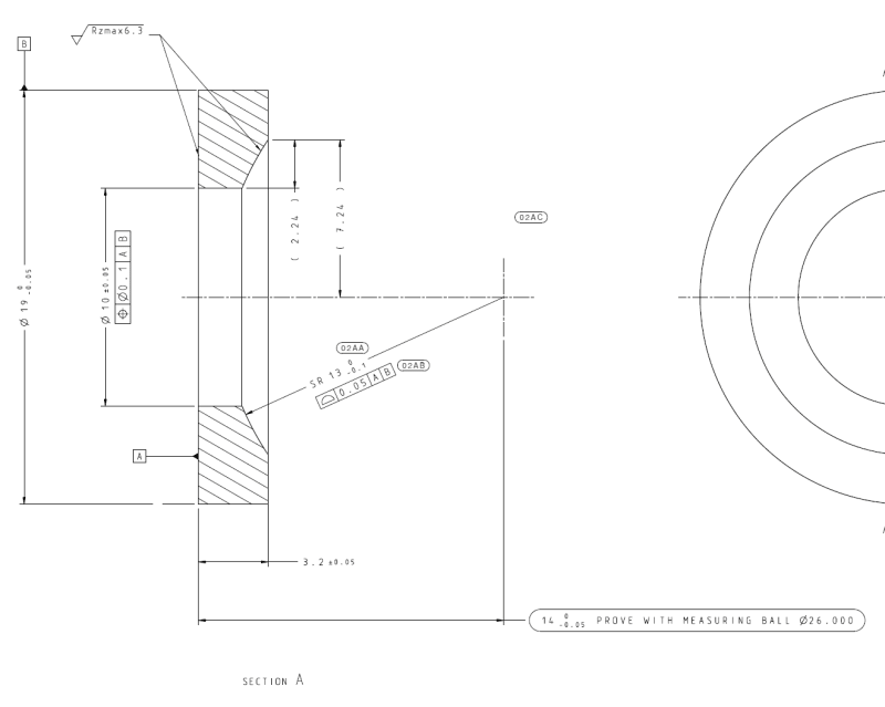
Now, back to my original topic, yesterday we sat down with the gage technicians and a product engineer and came up with a drawing that matches the function of the part and is measurable by our methods.
Here it is:
newss_g5x5iy.png


I have the geometrically controlled surface as Datum A.
Datum B is the axis of the outer dia, which is perpendicular to A, to ensure an ideal condition for CMM setup.
14 -0.05 height is directly toleranced. On CMM we check in an assembled position with an almost perfect gauge ball the height which is evaluated in the program.
SR13 -0.1 is positionally controlled by Datum B. We don't want the sphere center to move in Z direction (axis of the part), that's what 14 -0.05 is for. But there must be some allowance to move in X&Y.
Finally, the Profile 0.02 is refining the form.

Does this approach looks correct?
 
Wuzhee,
There is still a problem with the 0.02 profile tolerance applied to a contour that is not defined with basic spherical radius. There is also a problem that the position tolerance of 0.05 is applied to a feature that is not a feature of size, which, technically speaking, is illegal per Y14.5.

Additionally, if the position tolerance is 0.05 and the total tolerance for the 14 dimension is also 0.05, then why separate the two requirements? Why not change the 14 dimension to basic 13.975 and apply position tolerance of 0.05 relative to A|B with the spherical diameter modifier added in front of the tolerance value.

If the actual value of the radius is important to you, then you can specify it as an additional requirement to the profile tolerance and basic radius combo. (The other side of the story is that for arcs like this the standard does not give any recipe on how to obtain the actual radius value).
 
I thought there's still something that's off.

The idea was that position only applies around the axis of the part, while the direct tolerance gives the Z position.
This current drawing is based on the selected method of the gageroom. At first there weren't any profile or position tolerance on the part. The sphere surface was the problem, while it was OK at the height measurement for 14 -0.05 the part was scrapped because of the form deviation. (which we measured by CMM and an ink coloring method). Currently we are measuring every part and a 45minute CMM run isn't acceptable while the daily amount produced is over a few thousand.

Maybe I'm misinterpreting the ASME definition, but I thought that the sphere in this case is an irregular feature of size (by para 3.29 and 3.35.1/a). It also falls under 3.35.2 because it's a single directly toleranced spherical surface.

Please point me to the definition where I'm in the wrong, I'll be glad if I could understand it.
 
Yesterday we discussed various interpretations of the drawing and measurement, and they are unwilling to lose the height position (14 -0.05) because currently their checklist requires evaluation for that size.
I brought up the possibility of a spherical position tolerance to A|B and a profile tolerance on the sphere. They could calculate the height with CMM but it would require additional validation by the master gage technicians abroad and they're in the process of implementing a global measuring and gaging standard, so coming up with a completely different method and idea might be too much for them to accomplish now.
 
The problem with partial features that contain no opposed points is that a unique unrelated Actual Mating Envelope (AME) of the feature cannot be established (I wish the standard spelled it out more clearly). In other words, there is no point at which the expansion of the spherical envelope being inscribed within the partial spherical surface will be forced to stop, meaning that one will be able to expand the sphere even until it gets infinitely large. As you can imagine, this will heavily affect the location of the center point of the sphere.

In your case, since the location of the center point is arguably controlled by the combination of the two 0.05 tolerances, the effect described above may theoretically manifest in the actual spherical surface freely translating left and right, while having the same radius.
 
Alternatively, define the spherical surface to be datum feature A, based on a profile tolerance from a basic radius. Then the flat surface can have a profile tolerance to that spherical surface based on a basic dimension from the datum feature to the flat surface. That will be datum feature B. The outer edge a position tolerance to the combination of the two.

You can also specify the diameter of a datum target simulator for A, much as it currently calls for a measuring ball.
 
Pmarc,
The physical spherical ball / gage manufacturing tolerance is limited in size (not expanding) so that is the main argument on why this kind of measuring (and product definition scheme) is used and very popular in the industry.
I agree with you however that this proposed method and definition scheme does NOT fit the theory based on Y14.5 standard.

 
As noted above by pmarc, you should not specify a position tolerance on a partial spherical (or cylindrical) surface which is less than 180° and thus lacking any opposed points, because the center point (or axis) being controlled for position is the center of the "unrelated actual mating envelope" (UAME), and there is no robust UAME for such partial surfaces.

It is hard to suggest the best ASME Y14.5 tolerancing scheme without knowing the function of the part, how it mounts in the assembly, etc.
But if I were to interpret the design intent based on the current tolerancing and "translate" it to recommended practices supported by the standard, I would suggest making some of the directly toleranced dimensions basic, and implementing "multiple single segment" surface profile tolerances for the spherical feature, with some modified by the "dynamic" symbol (a triangle that follows the tol. value). In that sense, it is good that you have to follow the 2018 version of Y14.5, as dynamic profile wasn't available in the previous editions.

Here is my suggestion:
The spherical radius and the height to gage ball center would become basic SR12.95 and basic 13.975 respectively. The surface profile feature control frames would be as follows:

• First single segment: |Profile|0.1|
it is only meant as a replacement to the tolerance of the radius (note that it is not exactly equivalent to the direct tolerance though, it is a bit difficult to show why without preparing some graphics, but you can consider it as an alternative, or you can adjust the tol. value to what is appropriate). It would create a tolerance zone between two concentric theoretical spheres without any locational constraints, spaced apart by 0.1 mm and equally disposed about SR12.95.

• Second single segment: |Profile|0.05 Dynamic|A|B|
This tolerance would control the spherical fearute's surface within a tol. zone of two concentric theoretical spheres, the center point of which is located from datum A per the basic dim. 13.975 and centered to datum axis B per the implied basic zero dim. This will be your location control. Because of the dynamic profile modifier (a triangle after the tol. value), basic dim. SR12.95 would not apply to the definition of this tol. zone. The two concentric spheres defining the zone would be "flexible" in their radii to be able to contain an actual surface that has any radius within the range set by the first segment.

• Third segment: |Profile|0.02 Dynamic|
Since this one has the dynamic modifier as well, it would control the form without controlling the radius. Sort of like the spherical version of cylindricity.

You mentioned that you already have the ASME Y14.5-2018 PDF. See the definition and explanation of applications of dynamic profile in section 11.10 (page 244) and its subsections and figures 11-20 (second single segment of surface profile) and 11-35 to 11-38.
 
Letting the radius vary that much will allow mating along a line; might as well just use a cone and at least limit the line contact to the middle portion rather than allowing it to be anywhere, even along the edges of the part, which will form a stress concentration.
 
Wuzhee,
3DDave is correct in the point he brought up above. A 0.1 profile tolerance would allow far more variation of the radius value than a 0.1 direct tolerance stated by SR 13+0/-0.1. I underestimated the difference. To limit the radius value variation approximately the same as a direct tolerance would do (theoretically) you need to let the 0.02 profile tolerance limit the radius value as well. Then, the Dynamic profile modifier is no longer appropriate for this requirement, and therefore there is no point in having that modifier for the larger 0.05 locational profile with reference to A and B either.

So the suggestion changes to just surface profile within 0.05 unmodified with reference to A and B as the first single segment and surface profile within 0.02 unmodified without datum references for the second single segment. The 0.02 profile will control both the form of the sphere (limiting irregularities) and the radius value in a single requirement.

You indicated that it is difficult to implement this approach in your company, but this is anyway what in my opinion is the more unambiguous and correct way to specify the tolerances.
 
Thanks everyone, it's really helpful.
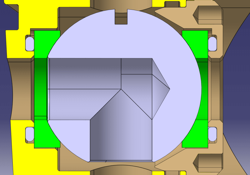
To put the topic in context here's the said part in it's environment. Half section of the assembly.
assss_da1exs.png

This is a ball valve in a vechicle refrigerant system. Green object is the part we're talking about atm. There's the steel ball in the middle. 2 of these seats, and an O ring behind them.
The function of this part is holding the ball in place and sealing the system. Our main problems right now is internal leakage of the refrigerand due to imperfect sealing profile. Hence the fuss around this green part.

3DDave, we tried cones before, tested it with multiple batches and suppliers. In the end the spherical sealing seat proved to be more effective and we continued with this design.

Burunduk, if I read everything right, my part would look like this:
newerss_ulmg9f.png

And the profile MSSFCF would mean this:
profile_thpisi.png


Am I right? (probably you are but I'm not sure I read your words correctly).
 
The cone was rather than using a really bad specification, not as an alternative for your use.

If it's fluid tight, I think the profile needs to be much tighter than you have specified.
 
Hi Wuzhee,
First off, considering the application you have shown, your datum structure is correct. It was the right thing to choose the flat face as the primary datum feature A and the OD as the secondary datum feature B. So you should keep that.

Regarding the dimensioning and tolerancing in your last image, yes - it is (almost) exactly what I suggested. The only difference is that I suggested using a "multiple single segment" (two single segments) surface profile tolerances, while you utilized a "composite" surface profile tolerance, HOWEVER - in this particular case, with just two segments and the second without datum references, it doesn't matter - the outcome is the same.
In other cases, you should be careful in differentiation between these methods and using the one that suits your design intent. Multiple single segment surface profile tolerances are just two or more profile tolerance feature control frames attached one beneath the other, like it is shown in figures 11-20 and 11-37 in Y14.5-2018. Each segment is just a regular profile requirement and the degrees of freedom are constrained by the datum references for each FCF as if it was a standalone specification. For the "composite" profile as you have specified and as shown in figures such as 11-36, where there is one common profile symbol for two or more segments, translational degrees of freedom are constrained only for the uppermost segment. A composite surface profile for a single feature is generally used when you want to refine orientation (and form) in the lower segments and let the uppermost govern location. In your case the second segment doesn't reference any datum features, therefore as I mentioned, the result is equivalent - in both methods the second segment is a refinement of form only. The tolerance zone + actual surface graphic you showed is correct for both cases (BTW, what does MSSFCF stand for? I haven't encountered this abbreviation before...)

As a side note, when preparing drawings to the ASME standard, set your drawing properties to display all dimensions horizontally and not according to the orientation of the dimension lines. See figure 4-16 on "reading directions" and sub-paragraph 4.4.5.2.
 
Status
Not open for further replies.
Back
Top