Continue to Site

Eng-Tips is the largest engineering community on the Internet

Intelligent Work Forums for Engineering Professionals

  • Congratulations GregLocock on being selected by the Eng-Tips community for having the most helpful posts in the forums last week. Way to Go!

Profile on Sheet Metal

Status
Not open for further replies.

marshell

Mechanical
Jun 6, 2003
63
I plan on using profile on the cut surfaces of sheet metal parts. Does the all around for the profile apply across the bends, or do I need to specify multiple profiles going from A<-->B, C<-->D, etc. where each call-out goes from bend to bend?

If I go from bend to bend, I would create a primary datum for each call-out that would correspond to the applicable plane that would have been the same plane as if it was the flat pattern.

Hope that makes sense, and thanks in advance.

 
Replies continue below

Recommended for you

To go "around the bend" use "all over" rather than "all around":

Sheet_Metal_Datums_cbqkqq.jpg


"For every expert there is an equal and opposite expert"
Arthur C. Clarke Profiles of the future
 
I don't know if every CAD system has it, but there is also a symbol for "All Over" you can use instead of the words.

All_Over_cpbgn9.png
 
marshell,

If your hole is located across a bend, the clearest presentation probably is to place dimensions and tolerance on the appropriate two views.

--
JHG
 
If using the "all over" call out on a sheet metal part, is it the "Unless Otherwise Specified" portion of the all over usage that would need to exempt the all over applying to the thickness, and the main faces? Does the sheet metal thickness tolerance, flatness, etc. still default back to the material specification? Can see the possibility of confusion, especially since the example that was shown has the profile pointing to one of these surfaces.

Other concerns I have with the "all over" on a sheet metal part is that I usually allow more tolerance on the bends, and in the bends reliefs (If I even care at all about the bends reliefs). There is also sometimes deformation that can take place in the bend area where obscure angles take place in the bend.

I am planning on doing the part definition as a hybrid model/drawing where basic dimensions are to be queried from the model, and want to make sure I have all my bases covered. Items like drawoh brings up are things I will need to deal with as each view of a hole across a bend may be referenced to different datums.

If I go with the A<-->B type profile going from bend to bend, then C<-->D to the next, etc. and if I am referencing different datums for each of these sections, I will then lose simultaneous requirements, and then will have to deal with relating each of these sections to each other.

I may be over thinking this, but again, just want to make sure I think everything through before going forwrard.

Thanks You.

 
marshell said:
If using the "all over" call out on a sheet metal part, is it the "Unless Otherwise Specified" portion of the all over usage that would need to exempt the all over applying to the thickness, and the main faces? Does the sheet metal thickness tolerance, flatness, etc. still default back to the material specification? Can see the possibility of confusion, especially since the example that was shown has the profile pointing to one of these surfaces.

The best way to specify thickness is to call it up as a regular dimension, with a tolerance. You make sure your thickness conforms to a sheet metal gauge. Consider making tolerances sloppy enough that more than one sheet metal gauge works. If your vendor cannot convert your specified thickness, get a new vendor. Dimensions with tolerances are inspectable.

marshell said:
I may be over thinking this, but again, just want to make sure I think everything through before going forwrard.

I claim that any idiot can prepare drawings for machining. On sheet metal, weldments, and castings, you need to understand how accurate the fabrication process is, you need to specify tolerances accordingly, and you need to assure that your sloppy design works.

--
JHG
 
Maybe I have not explained what I am trying to call out and define. I am trying to determine if the callout in the picture I included would be correct in defining the cut path of the sheet metal part. If the view and callout were in the flat pattern it would work, but am wanting to know if the defined profile of the cut path would still apply after forming, or if each section of the path (2 horizontal, one vertical) would need to be defined separately. Of course the picture is not fully defined for bend tolerance, radii, etc. I am concentrating my question on how defining the cutter path definition call out changes (or does not need to change) as it goes from flat to formed.

Thank you.

 
 https://files.engineering.com/getfile.aspx?folder=2e99ed7d-85ff-49c4-829c-983629ae41bb&file=Sheet_Metal_Profile.jpg
marshell,

It always helps to include a sketch where possible, it was somewhat ambiguous from your OP description what part of the bend you were talking about.

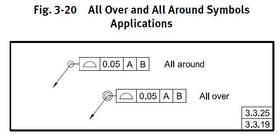
If you add the all-around symbol to your leader line on your profile callout, I see no reason that it wouldn't do exactly what you want - ie: control the cut edge all the way around. This is independent of the processing method used to create the part (ie: forming/bending). That said, are you using MBD or a 2D drawing? Typically all-around is attached to a view and applies "all-around" in the view specified, but I would think the intent here is clear enough even for MBD.

fig-3-20_la989c.jpg
 
Sorry about that. I meant to show the all around symbol in the picture.

The completed TDP drawings will be a hybrid that includes basic views, any +/- dimensions, GD&T, and directs the user to the cad model to query the basic dimensions.

 
marshell said:
Maybe I have not explained what I am trying to call out and define. I am trying to determine if the callout in the picture I included would be correct in defining the cut path of the sheet metal part...

The cut path of the sheet metal part is none of your business. Don't tell your fabricator how to do his job. You inspect the final bent part. If you allow for dimensions from sheet metal bends to have tolerances of [&pm;].015" or [&pm;]0.4mm, everything will be fine.

Sheet metal shops have asked me for my SolidWorks model so that they could flatten the part and mess with k[&nbsp;]factor. When you model sheet metal and you name features, consider the possibility that it will be outside your office in the hands of your fabricator.

--
JHG
 
Not trying to tell them how to make the part. I do not care if they uses an industrial strength paper cutter, plasma cutter, laser or waterjet, I am only defining the limits they must stay within on the finished part.

 
Status
Not open for further replies.

Part and Inventory Search

Sponsor