Continue to Site

Eng-Tips is the largest engineering community on the Internet

Intelligent Work Forums for Engineering Professionals

  • Congratulations KootK on being selected by the Eng-Tips community for having the most helpful posts in the forums last week. Way to Go!

Profile tolerance for outer rectangle surface

Status
Not open for further replies.

Sa-Ro

Industrial
Jul 15, 2019
273
Hi

I need to control the outer surface of the rectangle wrt bore as shown in image.
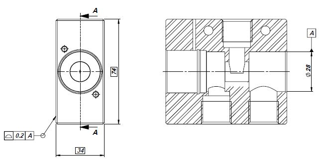
Profiel_tolerance_dby2rf.jpg


Requirement: Outer surfaces to be equally located from bore center.

Does the drawing representation right?

Thank you
 
Replies continue below

Recommended for you

You have to "clock" your Profile requirement, otherwise it can spin around the [A] axis, so relation between part outline and, for example, small holes is unclear.

"For every expert there is an equal and opposite expert"
Arthur C. Clarke Profiles of the future

 
Position the small holes to A as well for a simultaneous requirement control.
 
Hi, Sa-Ro:

This part looks like a solenoid body. Your datum A may be incomplete. You may have an A1 - A2 situation.

Best regards,

Alex
 
Or perhaps a candidate for 2X or even a continuous feature. A1 and A2 are meant for datum targets, where only a portion of a surface(s) is used to create a datum.

John-Paul Belanger
Certified Sr. GD&T Professional
Geometric Learning Systems
 
@Burunduk
Thank you

@CheckerHater
Small hole will be positioned wrt to datum A.

@ 3DDave
Small hole will be positioned wrt to datum A.

@ jassco
Yes. It is a solenoid body. Can you explain the A1 and A2 concept.

@ Belanger
Do you mean to provide datum B for opposite (to dia 28) bore and use datum A and B for profile tolerance?

Continuation question:
Next processing dept demanding for a dimension from datum A to outer surface of the rectangle. Since the outer surface is referred from datum A, there must be a dimension from that datum.

How to solve this doubt?

Thanks for all...
 
Shared centers have an implied zero dimension between them. That's why coaxial holes don't need a "0.00000" dimension between their centers.
 
Sa-Ro said:
@CheckerHater
Small hole will be positioned wrt to datum A.

@ 3DDave
Small hole will be positioned wrt to datum A.

This is not exactly GD&T related, but like GD&T it has to do with effective communication; If I may suggest a more concise approach to express it:

"@CheckerHater & @3DDave, Small hole will be positioned wrt to datum A."

BTW, excuse my ignorance, but what's the deal with the trend of using the '@' symbol before name/username of whom you speak to? As far as I know, '@' means 'at', which doesn't make sense to me in that context.
 
3DDave said:
Shared centers have an implied zero dimension between them. That's why coaxial holes don't need a "0.00000" dimension between their centers.

Can you provide any reference standards for this?

Burunduk said:
"@CheckerHater & @3DDave, Small hole will be positioned wrt to datum A."

Thank you for the suggestion.

Burunduk said:
what's the deal with the trend of using the '@' symbol

In whats app messaging application software, if we mentioned @ symbol the list of contacts will be displayed and the concerned person will be notified separately. Here I would like to mention that the reply is to the specific person.
 
Sa-Ro said:
In whats app messaging application software, if we mentioned @ symbol the list of contacts will be displayed and the concerned person will be notified separately
Cool! I didn't know that [blush].
Thanks for the tip.
 
Do you mean to provide datum B for opposite (to dia 28) bore and use datum A and B for profile tolerance?
No, that wasn't my suggestion, although they could be A and B and then hyphenated for use in the profile feature control frame.
If you're using ASME Y14.5, then the simplest solution would be the CF designation, which would define the datum as coming from the full bore (through) and it would also tackle the issue of locating those 28 diameters to each other.
I don't know the function, and I don't know what the full drawing looks like -- maybe that issue has already been controlled.

John-Paul Belanger
Certified Sr. GD&T Professional
Geometric Learning Systems
 
Belanger said:
If you're using ASME Y14.5, then the simplest solution would be the CF designation, which would define the datum as coming from the full bore (through) and it would also tackle the issue of locating those 28 diameters to each other.

Another solution would be to specify "2X" before the diameter 28 dimension and apply a position tolerance without datum references to that dimension (possibly with the value of 0@MMC, then it should be equivalent to the CF application). Then the datum feature A symbol can be attached to the position feature control frame or aligned with the dimension of the 28 diameter to indicate that the two nominally coaxial bores form datum feature A together.
 
Sa-Ro,
Another minor issue is that if you are working according to ASME Y14.5, the dimensions should be displayed differently: they need to be read horizontally.

If you're using ISO standards, then some of the guidance you received above in this entire thread is either irrelevant or incomplete (it is only ASME compliant).
 
Can you provide any reference standards for this?

The standards are the rule book. If you don't have a copy to refer to then you need to get one.
 
Belanger said:
simplest solution would be the CF designation
I am using ASME Y14.5:2018 standard.

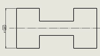
I have seen examples for CF as below.
Capture_1_qdvznc.jpg


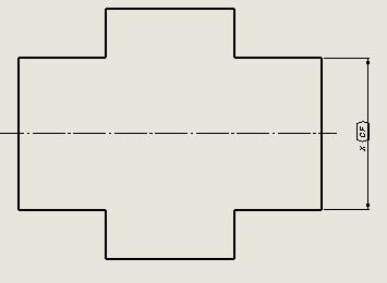
Is it possible to use CF as below?
Capture_2_zpfyce.jpg


As per ASME Y14.5:2018, para 3.10 and 3.11 CF defined as "two or more interrupted features". Till date I thought of interrupted by material removal.

Burunduk said:
specify "2X" before the diameter 28 dimension
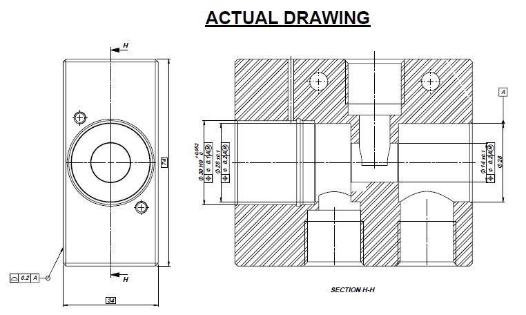
My bores are different in size Dia 28 and dia 30

Capture_evdmpy.jpg

To accommodate many dimension in less space, I am using dimensions aligned vertically.

3DDave said:
standards are the rule book
I have ASME Y14.5:2018 book. But unable to locate the guideline for implied zero dimension for linear.

Thank you.
 
Hi, Sa-Ro:

The second image you posted is not considered a CF as they are two separate features. You will need to use "Multiple Datum". You can use either A - B, A1 - A2, or X - Y to label them as multiple datum in your FCF. There is an image (Fig.7-16) on page 78 in ASME Y14.5-2018 that shows this application. You can also refer to Fig. 4-4 and 4-23 in ASME Y14.5-2009.

Best regards,

Alex


jassco said:
You can use either A - B, A1 - A2, or X - Y to label them as multiple datum in your FCF
I disagree with A1 - A2 in an FCF. "A1" and "A2" may only be datum targets labeling datum feature "A".
 
Jassco said:
The second image you posted is not considered a CF as they are two separate features.

Thank you
 
Status
Not open for further replies.

Part and Inventory Search

Sponsor