Eng-Tips is the largest engineering community on the Internet

Intelligent Work Forums for Engineering Professionals

Profile Tolerance interpretation - Location control 1

Status
Not open for further replies.

Ambro92

Mechanical
Jun 1, 2022
1
0
0
IT
Hello everyone,
I have an issue about the interpretation on one of our component drawing.
It's a complex component, semifinished casting, which dimensions have to be checked.
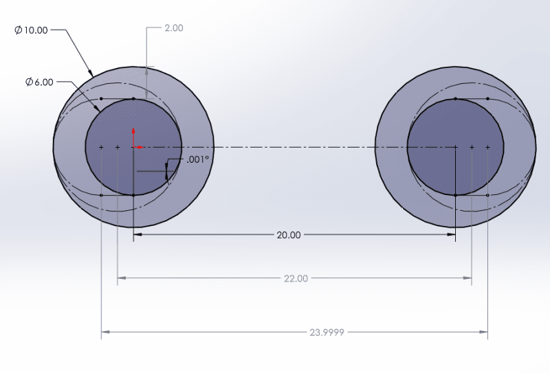
On the drawing an overall profile tolerance is applied on every feature(2mm respect to A-B-C Datum). I attach a simple image to explain:

Cattura_kroxny.png


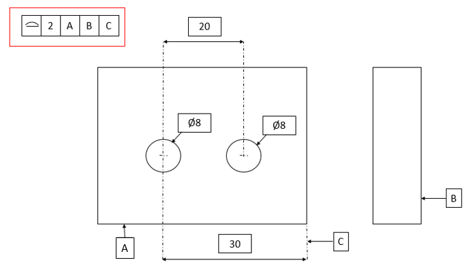
In order to be aligned with the supplier, which is the tolerance value to be considered on the 20 mm dimension (hole distance)?
I know that should have been better to choose a location tolerance for holes.
Can profile tolerance be used for location control?
If so, I think that the result should be 20 +/- 2 mm. Am I right?

Thanks to everyone who will help me.

Nicola
 
Replies continue below

Recommended for you

I think is more usefull to think about the outer and inner limits (outermost and innermost boundaries) are represented by Ø8±2.
Then, also the perfect form at MMC and perfect form at LMC are both applicable. Again, for the profile tolerance think in terms of where suppose to be material and where supposed to be lack of material (void)


A boxed dimension (called "basic dimension" in ASME and "theoretically exact dimension" in ISO) does not get a tolerance. As greenimi stated, a "profile of a surface" tolerance applies to boundaries (or surfaces).
So think of the 2 mm as imaginary bands scribed around each hole's wall -- 1 mm inward and 1 mm outward. In the end, the max distance between the holes is affected by the profile tolerance (it could become 22 mm max), but you don't really want to think of it that way because a portion of the profile tolerance will also be absorbed by form, size, and orientation errors of each hole.
 
Ambro92,

As greenimi has suggested, profile and position are not interchangeable as they control different aspects of a feature. See below for an example of what I mean. The nice dotted circles are if we assume the feature has perfect form, in that case your largest position deviation is as you said (20+/-2). However if we introduce some form error, we can get up to 20+/-4 position deviation - at least theoretically, I made the walls for this example at a .001° angle so your UAME is unambiguous so the distance shows 23.9999.

Moral of the story, don't expect profile to translate directly to a particular amount of position deviation as the way they control a feature are totally different - there is almost never a 1:1 relationship between the two (except perhaps for planar/width shaped features? I'd have to dive into it more though).

Also, you didn't state what standard you adhere to but obligatory side note - your datum features are self referencing, so if you go by ASME Y14.5 (not explicit in 2009 but the prevailing interpretation, however codified in 2018) the available tolerance zone for the planar features A, B, and C will be halved. I'm not sure how this is handled in ISO.

pos_error_wrtprd.png
 
Status
Not open for further replies.
Back
Top