Continue to Site

Eng-Tips is the largest engineering community on the Internet

Intelligent Work Forums for Engineering Professionals

  • Congratulations pierreick on being selected by the Eng-Tips community for having the most helpful posts in the forums last week. Way to Go!

Profile Tolerance Question (Inside offset conflicting tolerance block)

Status
Not open for further replies.

Gizmod

Industrial
Dec 4, 2020
3
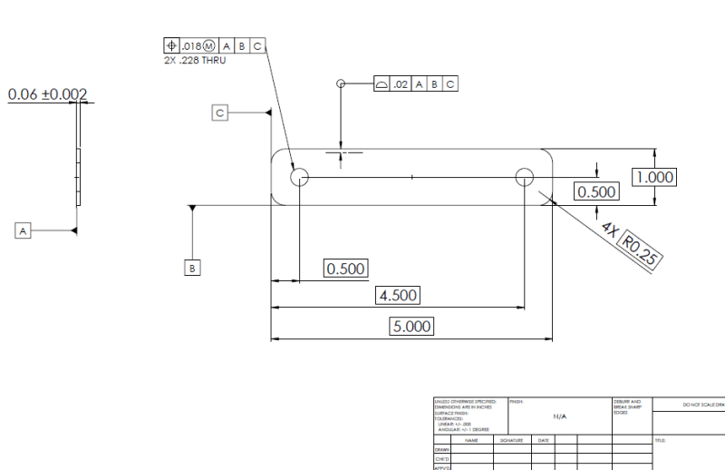
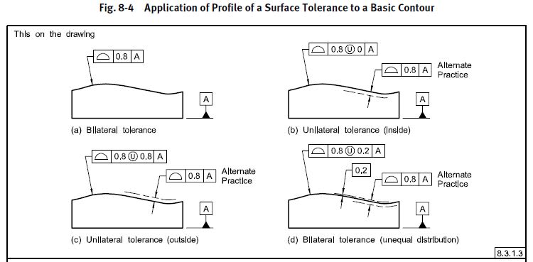
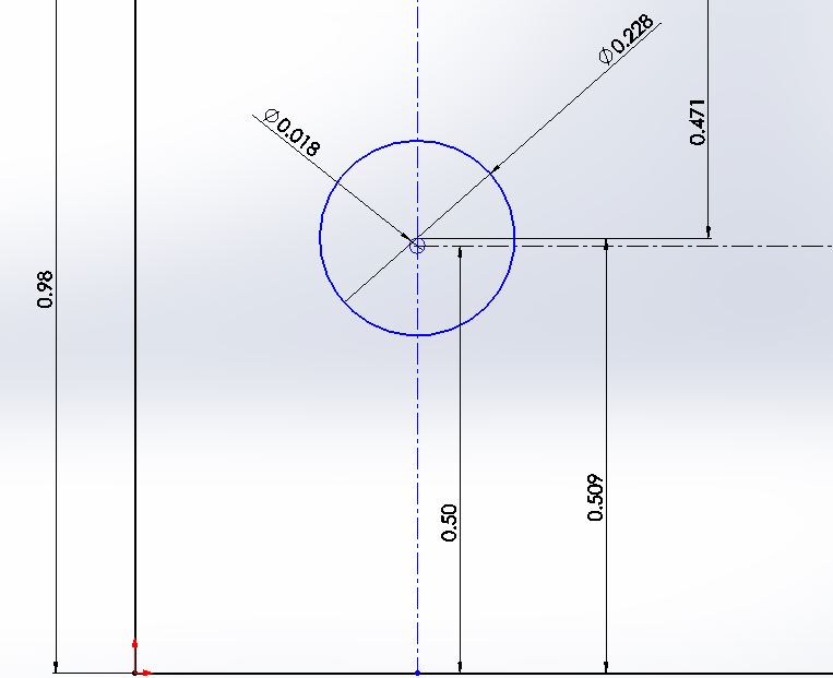
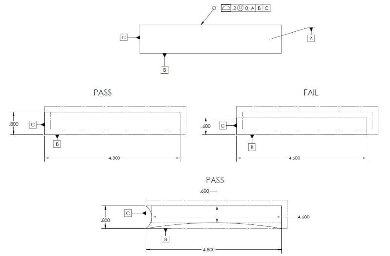
Hi guys. First time poster but a long time lurker on this forum. We recently made parts for a customer who is rejecting these parts stating that the profile tolerance was OOT when they received the parts. The receiving QC stated the profile tolerance of .02 was out .0242 and stated 1.00 basic dim measured 1.0042. This has me confused and I want to start by apologizing for my ignorance on the subject. It is pretty rare I come across profile tolerances. My initial understanding is that since three place decimals on the print are toleranced at +/- .005 this part would be impossible to make with an out of tolerance profile beacuse... well if you keep the width in tolerance (.005) then the profile would be within .02. Now after reading forums and looking at the ASME handbook I am fairly certain I was wrong with my initial assumption. Since the profile callout has an offset line only on the inside of the profile that means any dimension over the 1.00 would make the profile tolerance OOT. So this leads me to a few questions: Am i correct that the width can not be over 1.00? Do I need to hold +/-.005 on the 1.000 dimension still? Or is the tolerance block irrelevant since all dimensions are basic?
2020-12-04_08_55_39-Window_trm6xx.png
 
Replies continue below

Recommended for you

Title block tolerances apply to untoleranced non-basic non-reference dimensions only. There are none such on this drawing.
You are correct that the width can't be over 1.00.
 
The 1.000 has a box around it; this is called a basic dimension. The purpose of a basic dim is to set up a theoretical dimension, and you cannot appeal to the general tolerance. Thus, the ±.005 is not to be observed. Instead, the profile tolerance kicks in (all the way around the perimeter, because of the small circle on the elbow of the leader line). And in this case, because there is a phantom line scribed inside the outline of the part, the profile tolerance of .02 is entirely inside the theoretical perimeter.
So anything over 1.000 is indeed a reject.

John-Paul Belanger
Certified Sr. GD&T Professional
Geometric Learning Systems
 
Am i correct that the width can not be over 1.00?

Yes. Looks like you have a unilateral/unequally disposed profile tolerance applied which means the width you are referring to can vary at its extremes between 1.000 and 0.960 when constrained to datum features |A|B|C|. That last part is important as your width can come in between this range but if when constrained to the applicable datum features it could be out of tolerance (because of errors in form/orientation/location not just size).

Looks like your part is indeed out of tolerance as it measures 1.0042 which is greater than 1.

As a side note, either purposefully or by accident you have self referencing datum features (profile to |A|B|C| also controls the profile of A and B). Since you have a unilateral tolerance, this doesn't really create an issue since the tolerance zone is entirely "inside the material" and the entire tolerance zone may be used, its just something to be aware of.

Do I need to hold +/-.005 on the 1.000 dimension still?

This is a resounding NO. General tolerances do not apply to basic dimensions, they are by definition theoretically perfect and determine the basic (theoretically perfect) location/orientation/size/form of your profile tolerance zone. Your actual part/feature(s) (imperfect) must fall within this zone.

You can read a bit more about this in an earlier thread, which discusses some of the definitions of basic dimensions.


A side note - there is a newer method for denoting unilateral profile tolerances with the circle (U) symbol. Y14.5-2009 provides the notation shown in your drawing as "alternate practice" however Y14.5-2018 has removed it altogether. Thats not to say that we can't interpret what is meant, of course we can, but something to note that there is an updated way to specify this and it no longer appears on the new version of the standard. Below is the old figure from Y14.5-2009.

fig_8-4_duq9kg.jpg
 
chez311 said:
Yes. Looks like you have a unilateral/unequally disposed profile tolerance applied which means the width you are referring to can vary at its extremes between 1.000 and 0.960 when constrained to datum features |A|B|C|. That last part is important as your width can come in between this range but if when constrained to the applicable datum features it could be out of tolerance (because of errors in form/orientation/location not just size).

So I basically have no choice but to make this part asymmetrical since the width needs to be under 1.00 but the holes still need to be .50 away from the edges. That to me seems like a design flaw since the part was obviously modeled to be symmetric. What would be the design alternative to keep the part symmetrical while maintaining the profile tolerance? Make datums B & C the theoretical CL?
 
You could make the (centerplane of) the 1.000 width datum B instead of a surface, maintaining symmetry.

"Know the rules well, so you can break them effectively."
-Dalai Lama XIV
 
the width needs to be under 1.00 but the holes still need to be .50 away from the edges

The 2x .018 wide tolerance zones for the 2x holes are located .500 basic away from the bottom face that means at worst case the holes' axes could be .509 from the bottom face and .451*.471 from the top face. Thats a difference of .058* .038 - so as you noted the potential variation could be somewhat asymmetric, which may not be what the designer intended.

As ewh noted a potential solution could be to attach the datum feature symbol to the width to derive a center plane datum, however as I previously mentioned with the self-referencing datum feature that makes your tolerance zone a bit more...well at least more difficult to interpret.

The ultimate design solution depends on how exactly this part functions. If the outside dimension is truly a critical interface then a datumless profile tolerance could be applied and everything else driven from there (B and C applied to the face or width depending on whats appropriate). My guess is that the holes are more likely the more critical features. In that case I would either derive B and C from the holes either separately or a pattern (again, depending on whats appropriate). The third, and sometimes more palatable solution is to simply apply position/profiles tolerances to |A| which are held by default in ASME in simultaneous requirements (SIM REQ) to each other.

Below is a rough sketch of the worst case variation of the holes axis as defined in the drawing you provided.

*Edit - my mistake. The maximum distance to the top edge from the datum feature simulator for B as shown in your drawing is .98 instead of .96 as I showed prior to the edit. Your width may vary to .96 due to form variations however no point on the far (top) edge may be closer to the planar datum feature simulator for B than .98 due to the profile tolerance (form variation could make that a little more confusing though as it could allow some points along the datum feature B, but not the datum feature simulator itself, to be closer to the holes). Hopefully that makes sense.

tolzone_rough_vksdad.jpg
 
So I basically have no choice but to make this part asymmetrical since the width needs to be under 1.00 but the holes still need to be .50 away from the edges.
Based on the drawing you've given, yes it may be asymmetrical. But so what?
However, if the design requirement is that the holes need to be symmetrical across that width, then the width should have been designated as datum feature B. But then they might not be .50 from that one surface.

In other words, you can't have it both ways (unless the part is made perfect).

John-Paul Belanger
Certified Sr. GD&T Professional
Geometric Learning Systems
 
Totally agree with Belanger and chez311. Keep in mind that profile of a surface is also controlled on both sides of the part. Since the POAS says .02 inches. The part will pass if it is 1.000" - .960" (.02" times 2).

This tolerance (.02" times 2) will also be applied to all outside dimensions. In other words, your part may get smaller by .04" all around. But it can not get any bigger than the stated dimensions.

Which is a shorted version of what has already been stated above.
 
In other words, your part may get smaller by .04" all around. But it can not get any bigger than the stated dimensions.

I want to add a caveat to this, its the reason for my (admittedly somewhat confusing) addendum/edit on my post (4 Dec 20 16:43). Perhaps I can clarify that with a sketch or two.

As a result of the aforementioned self referencing datum features* while it may look like the width may vary within the entire profile tolerance it cannot do so uniformly all around - ie: the profile may be .96 somewhere along its length but it must measure at or greater than .98 somewhere (or more accurately, fall within the stated unilateral profile tolerance zone when constrained to |A|B|C|), otherwise it will not pass.

To show this more clearly, I have come up with the figure below and adjusted the tolerance by a factor of 10 (.2 instead of .02) so you can easily see the differences. The same concepts apply to your original drawing, just not as exaggerated of course. Note that when the width is uniformly .8 and 4.8 it passes, but when it is uniformly .6 and 4.6 it fails - even though the bounds of the tolerance zone are .6 and 4.6 (the dotted/construction lines in each figure). This is due to the way B and C are simulated - they must make contact with their respective simulators. The second pass case is when there is form variation which causes the part to measure .6 and 4.6 somewhere along its length but not everywhere.

Hopefully this makes sense and is helpful!

SELF_REF_PROF_v4tmci.jpg


*Theres some debate on the actual use of this term - in this case I'm just using it to refer to datum features which are controlled by a tolerance which is referenced in its own FCF. In this case a profile tolerance to |A|B|C| controls the profile for B and C.

 
chez311 said:
....in this case I'm just using it to refer to datum features which are controlled by a tolerance which is referenced in its own FCF. In this case a profile tolerance to |A|B|C| controls the profile for B and C.

Chez311,

Haven't we concluded that toleances halves?
 
3DDave,
Yes, You are correct.
Only on the bilateral profile the tolerances are halved.
Thank you for straightened me out.

 
3DDave is of course correct.

Just for OP's reference, here is the applicable section in Y14.5-2018 where this has been officially codified (it was the general consensus on interpretation prior to 2018). The case of interest is the (b) below:

ASME Y14.5-2018 said:
11.4.3.1 When the Toleranced Feature Is a Nonsize Datum Feature.
At the datum feature, the distance to the true profile is zero. Since the datum feature may not pass through the datum plane, the tolerance on the considered feature shall be as follows:
(a) For an equal bilateral profile tolerance, half of the profile tolerance is available for variation of the datum feature. See Figure 11-21.
(b) For a unilateral profile tolerance, the tolerance may only be applied into the material of the feature.
 
chez311 said:
Just for OP's reference, here is the applicable section in Y14.5-2018 where this has been officially codified (it was the general consensus on interpretation prior to 2018). The case of interest is the (b) below:

I was looking at Y14.5-2009 when I initially began looking into this. Y14.5-2018 describes everything so much better thank you for the reference.
 
Gizmod,

Glad I could help. Hopefully the figure makes sense too, its sort of a strange case and in my opinion it should typically be avoided if possible but there are cases where one might want it. Often though it just comes from people not realizing that they created such a reference and/or not knowing the implications.
 
Status
Not open for further replies.

Part and Inventory Search

Sponsor