Continue to Site

Eng-Tips is the largest engineering community on the Internet

Intelligent Work Forums for Engineering Professionals

  • Congratulations KootK on being selected by the Eng-Tips community for having the most helpful posts in the forums last week. Way to Go!

Profile Tolerance to 3 places with defining dimensions to 4 places 1

Status
Not open for further replies.

MoreCowbell45

Mechanical
Mar 27, 2024
7
Can anyone explain why you would have a 3 place profile tolerance but than all the defining geometry is 4 places. I have yet to try to explain fully why this is a bad practice and it only control you to 3 places. my Peers say to just do it but i believe its not correct. I need more back up information on why its a bad practice.
 
Replies continue below

Recommended for you

The answer might depend on whether you're using inches or mm (and which tolerancing standard you're using). If you have access to the ASME Y14.5 standard (2018 edition), check out paragraphs 5.3.1(d) and 5.3.2(d).

John-Paul Belanger
Certified Sr. GD&T Professional
Geometric Learning Systems
 
Thank you its inches. we have some very tight profiles and i have some that think holding the dimensions tighter than the profile will get a better part.

 
In short - all dimensions are taken as if they are followed by an infinite number of trailing zeros. Y14.5 has some arcane reason for directly applied tolerances having the same number of digits, padded by zeros if required, as the base dimension, but that doesn't apply to geometric characteristic tolerances as are applied in feature control frames.
 
Do you mean the basic dimensions that define the true profile? It doesn't matter unless there are fewer decimal places because of some rounding and they end up with different values. But other than that, .500 is the same as .5000 etc.
 
Dimensions aren't "held." They are the basis to which other measurements are compared. Variation is what is held.
 
MoreCowbell45 said:
we have some very tight profiles and i have some that think holding the dimensions tighter than the profile will get a better part.
The dimensions defining the geometry that then gets a profile tolerance should not be tight or loose -- they should be theoretically exact (i.e., basic dimensions).
So it may be a non-argument after all (or else a lot of confusion about profile's rules!).

John-Paul Belanger
Certified Sr. GD&T Professional
Geometric Learning Systems
 
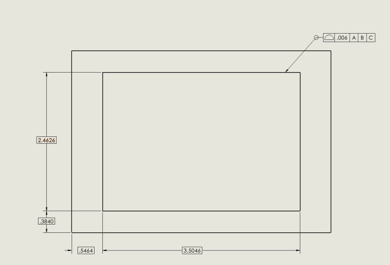
Say the Profile is .006 around and the points being called out are such 1.8220 Basic, 2.3750 Basic, 2.654 basic to define this area and even the radius is 4 places to .0625.
 
If you feel any better that tolerance is equivalent to .006000000000000000000000000000000000000000000000000000000000000000000000000000000000000000000000000
Though past about 12 digits it's down around the diameter allowed to a carbon atom diameter (there is some disagreement on how any atom diameter is measured.)
 
So what is being said here is no, the 4 place dimensions do not matter because we just have a .006 tolerance zone?

SAMPLE_1_alnzwq.jpg
 
They don't matter in terms of tolerance, that's correct.
There's no direct tolerance on basic dims (even if the title block provides a default +/- on 4-place dimensions).
And based on paragraph 5.3.2(d) that I quoted above, it seems that the profile tolerance of .006 is fine as it currently is. So the current drawing is good (well, assuming the datum features are labeled, etc.).

John-Paul Belanger
Certified Sr. GD&T Professional
Geometric Learning Systems
 
Anyone who gripes about the number of digits in a basic dimension does not understand what it means.
 
I'd be the one griping since my past practices to match the decimal places. I trying to understand Y14.5 better and this is a great way to understand from people who really understand GD&T and use it daily
 
Basic dimensions can be to any number of decimal places.

All tolerances related to a basic dimension must come from feature control frames, often profile and/or positional tolerance.

I like to think about dimensioning a hole location that's 1-7/8" from the edge and needs to be located within 1/4". Simple enough with a tape measure and rectilinear dimensions and tolerances.

With GD&T, you could do a similar tolerance using a basic dimension [1.875] and positional tolerance with a value of .25. It's convenient to have the extra decimals on the basics, because when I build my models and do my stackup analyses I don't have dimensions being rounded up and down to fit the number of decimals.
 
Status
Not open for further replies.

Part and Inventory Search

Sponsor