Continue to Site

Eng-Tips is the largest engineering community on the Internet

Intelligent Work Forums for Engineering Professionals

  • Congratulations cowski on being selected by the Eng-Tips community for having the most helpful posts in the forums last week. Way to Go!

Profile Tolerance Woes [img https:

Status
Not open for further replies.

Loki700

Aerospace
Jul 15, 2021
8
Profile Tolerance Woes
Gtols_qneqge.png

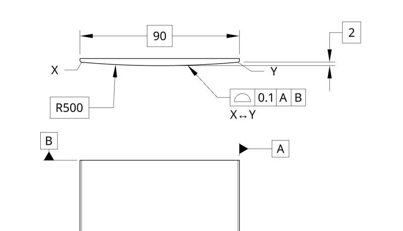
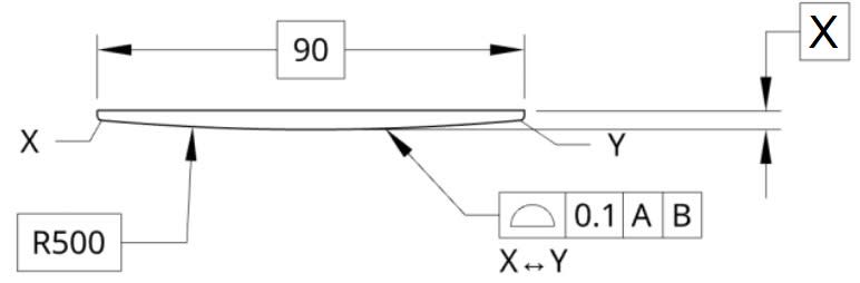
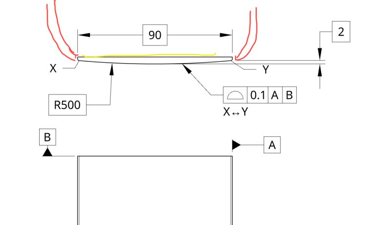
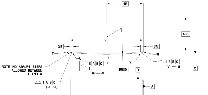
Hey, so I want to make sure I'm not incorrect. I've got a print that is similar to the above and it seems to me that the radius dimension could float from 499.95 to 500.05. The vertical dimension I don't see as necessarily having a tolerance, unless that would also be 1.95 to 2.05? I'm unsure on that one. I know that it's surfaces within that range, but thinking about it in limits of basic dimensions helps me visualize it.

However, the horizontal dimension, 90, shouldn't be basic, correct? It essentially has a tolerance of +/-0 since there's no GTOL related to this dimension from what I can see. For reference, I didn't create this print and I'm just trying to figure out what the person who drew it, who's no longer with the company, was thinking and ensure I'm not missing something obvious. Also the tolerance is crazy small for a part like this.

The main reason I ask all of this is because how this part was INSPECTED was with a radius of 500+/-0 and then the surface profile was taken separately with a tolerance of +0/-0.1. It should have been related to the 500 radius on the CMM, correct? Also the other two dimensions weren't inspected, but I'm still convinced that 90 shouldn't be basic, and I'm thinking that 2 shouldn't be either.

I'm looking to open the tolerance on this part, and what I THINK makes sense is to make the 90 a normal dimension, make the 2 a normal dimension, then make the profile tolerance something like 10. If I were to keep it how it is now and made the tolerance 10, that would make it 495 to 505 for the radius, but that would also make the 2 dimension range from -8 to 12 right? The 90 dimension would be unchanged from what I can tell.

I've been staring at this part for too long, so any help would be greatly appreciated. There are other dimensions on the print, but these are the only GTOLs on the print, and it just seems like a bad implementation of them to me. I hope I've made sense in my rambling.
 
Replies continue below

Recommended for you

The radius has no tolerance. The surface has an allowable deviation from the perfect form. The actual surface could be made of a series of flats (infinite radius) with sharp corners (zero radius) or it could have a series of scallops (negative relative radius) and still meet the requirement.

This is the advantage/disadvantage of the profile of surface geometric characteristic control.

From your description it sounds like that part of the inspection was done correctly.

edit - except it should have been +.05/-.05 deviation from the [R 500] as the default tolerance is the total width, equally disposed on either side of the nominal surface.

With the selection of the datum features depicted and the way they are used in the feature control frame, I'd say that this application has enough wrong with it to make further suggestions useless without seeing what the part is supposed to do.

The [2] is an attempt, maybe, to set the horizontal location of the radius. I think it is insufficient, but being basic isn't the problem and neither is it for the [90] dimension. Neither has a tolerance and neither should be inspected.
 
3DDave, thanks for the quick reply!

Thanks for also confirming what I thought, which is that there’s a lot wrong with this, I’m going to have the 90 and the 2 removed as basic dimensions.

I had this thrown in my lap and it’s been frustrating me and thinking I don’t know how to read GTOLs since this made it to production in such a large company.

It’s effectively part of a cosmetic enclosure that mates up to similarly formed parts on the sides to make it a smooth transition so it’s aesthetically pleasing.

With that in mind, the actual radius of the part isn’t that critical as it’s so large and small deviations won’t make or break the look of the part.

It’s been a while since I’ve had to look at CMM reports so I forgot if the tolerance would be applied to that radius, but we were getting parts failing because they weren’t “exactly” [500], which seemed wrong to me.

You’ve helped right my ship though, I think I know where to go from here. Thanks again!
 
Wait - what? Removing the basic symbol won't come close to fixing this and doing so adds more problems than it can fix.
 
The designer intent on the basic dim 2 is to locate the radius R500, you can't remove it. But it is very hard to measure this basic dimension indeed, I will make a minor change as shown below for easy inspection.

2021-07-15_204137_c9thsm.jpg


Season
 
To make the basic dimension 2 meaningful for locating the radius feature, the primary datum feature A should be the large flat surface opposing the radius. It is probably also the interface feature that makes the most contact with the mating part and plays the most important role in this part's final orientation, so I think that would make sense.
 
Ok, that makes sense that I can’t remove the [2] dimension completely, I was just referring to removing it’s stays as a basic dimension. Let’s say I want a functional tolerance of [500] +/- 5 and [2]+/-0.05. How would I communicate that without making [2] a normal dimension of 2+/-0.05?

Really the only way I can think of to communicate that would be to have the following dimensions:
[500] with a profile tolerance of 10, then non basic dimensions 2+/-0.05 and X+/-0.05.

Without having both X and 2 dimensions, opening the tolerance on the profile allows that intersection to float 5 in either direction, which won’t satisfy the requirement of mating up to the other parts. To show this I’ve added the mating parts below in red. These are all stamped sheet metal, so adding a datum C to the surface I’ve marked in yellow I don’t think will be feasible as that’s the edge of the sheet metal; there’s no return flange.
7B8B5D0F-4C3C-4EE9-9F76-84EB37A58F6F_ugsla0.jpg


To give you an idea of how this part looks, here’s a 3D view:
99843B9F-CA9B-4525-99F1-180F14C86465_tbm6hy.jpg
 
Loki700,

In order to have a complete, correct and unambiguous PROFILE requirements you shall have a basic dimension and not a ± dimension.

By the way, which standard is governing your drawing?

If ASME (2009):"A true profile is a profile defined by basic radii, basic angular dimensions, basic coordinate dimensions, basic size dimensions, undimensioned drawings, formulas, or mathematical data, including design models."
 
Also, you can use composite profile (only if needed) to give more tolerance for location and less tolerance for size/ form.
Or per ASME (2018) standard you can break the size and form by using the "delta" symbol (and then the lower segment will control form only) and the size will still be controlled by the upper segment.

There are options around................
 
Ok, so it's a formed sheet metal part, so a datum C or moving datum A is functionally useless.

greenimi, to clarify we're using AMSE (1994). Also, the problem with what you've stated is that a composite profile tolerance won't accomplish what is wanted. I don't care so much about the size/form, because the radius is huge, so if it's a bit rounder or a bit flatter, I don't care because it will look the same, which is the important part. What I DO care about is the actual position of the end of the radius, so that it mates up to the other stamped components on the sides. To give you an idea of the actual tolerance zone I want to achieve, I've mocked up what I want, where the radius can float more, but the position of the transition to the other parts is constrained more.
tolerance_band_wkxdwr.png


I'm starting to think that this drawing would be better suited to not have GTOLs to define this...
 
You mentioned that you work per the 94' ASME standard. Would it be a big problem if you referenced the 09' version on this drawing? It has the non-uniform profile tolerance zone and I think it suits your design intent:
Screenshot_20210716-184957_Drive_pd2vm6.jpg
 
Burunduk, that's perfect! Our standard block calls out '94, and technically we aren't supposed to change it, but I'll see if there's any chance we can make an exception. I guarantee our quality department won't like it but we have the standard on file, we just never use it...
 
Glad to be of help.
Also, since you don't have a datum feature that can constrain the floating of the [500] radius in the direction that enlarges or reduces the [2] dimension, and you are considering to make the [2] a toleranced dimension, if you do so consider using the Dimension Orgin symbol instead of the arrohead that meets the extension line from the straight 4 edges of the sheet metal. This will communicate to inspection that the part should be rested on the surface plate on the straight side and the measurement should be to the top of the radius. Although inspection will probably figure out it's the only practical way to measure it anyway, but it will make your specification more unambiguous for this kind of a +/- dim.
 
Alternatively - use datum targets on the end points as a basis to locate the mating surfaces. Then there isn't any other tolerance buildup.
 
3DDave, that's a good idea I hadn't considered, thanks.

The bad news is that I've hit a wall with using 2009; we're stuck with 1994 for the time being to avoid confusion which I get. We're supposed to be making the jump when we switch modeling software versions.

With that, I'm again at a bit of a loss of how to dimension this with GD&T. I'm going to scrub through the standard again (if I can locate the 1994 version in our resources....) and reacquaint myself with the standard as it's become clear that I know less about GD&T than I thought I did. Classic Dunning Kruger syndrome I guess.

Thanks everyone for your help thus far, and if anyone has any further insight/tips on how to accomplish this I welcome it.
 
Loki700 said:
Classic Dunning Kruger syndrome I guess

Interesting. We all are affected by this. Some more, some less. The first step for cure is to be aware/ conscient of its existance.


Regarding 1994 verus 2009 standards issue: you can use a note on your drawing stating that "this callout--let's say the non-uniform profile tolerance zone- is per ASME Y14.5-2009" (even the rest of the drawing stays in 1994 version).
 
Hi, Loki700:

From this statement below,

"the radius dimension could float from 499.95 to 500.05."

it seems to me that you don't realize that dimension R500 BASIC is NOT a specification. Because it is NOT a specification, you don't have upper (USL) and lower (LSL) limits for this dimension. You are not supposed to inspect or evaluate this BASIC dimension. R500 BASIC is here to support for definition of the profile of surface (0.1) in reference datum A and C.

Best regards,

Alex
 
jassco,

You would be correct, I had forgotten that basic dimensions weren't specifications because for the past 5 years all of my GD&T involvement has just been positional tolerances really, and I haven't been involved in any inspections because that fell to the manufacturing engineers at my previous position. This was compounded by the fact that our quality department reported the R500 and considered it a failure, and the fact that I've been doing more analysis and less drawing work the past 5 years. It's been a very humbling experience.

This is what I meant in my last post about how it was clear that I didn't know as much about GD&T as I thought I did, and the more I learned the clearer that became. I took some time to try to learn and reacquaint myself with everything I had forgotten, and things I just flat out never really learned so I could have a more constructive conversation, and so that I'd be less likely to embarrass myself again.

I took another whack at dimensioning this using different profile tolerances on segments of a profile. This way I could control the ends of the feature where it really matters for blending with the mating parts, and then it can be opened up in the center where position isn't as important, with a composite tolerance to control form. This drawing is a mess and is not at all how it's going to look in its final form (whipped it up in the spare 10 min I had today), but I'd like to get some feedback on this type of dimensioning and if it seems to make sense or not. I'm sure it's not perfect, so any tips or corrections would be greatly appreciated.

NEW_PROFILE_f1gbpq.png
 
Msking "C" the tertiary datum feature means it can contact at only one point because the main orientation is from the tiny surfaces identified with [A] and .

It tells the inspector - clamp that surface identified with [A] to the granite surface plate and then put an angle plate up to the surface identified with [B} and finally bring a second angle plate to firm contact with the surface plate and the first angle plate and slide it to just touch the surface identified as [C]. The surface plate and the two surfaces of the angle plates are the origins of the basic dimensions.
 
Using datum features A (or B) as a primary datum would be like trying to balance a credit card on its edge (quote from one of late Don's GD&T tips).

Your primary datum will be of sufficient size(datum feature C) instead of a narrow edge(datum feature A or B), since the datum feature A or B will have an unstable set-up on the granite surface plate, so I will recommend to make a change from |A|B|C| to |C|A|B| or |C|B|A|

Season
 
Status
Not open for further replies.

Part and Inventory Search

Sponsor