Loki700
Aerospace
- Jul 15, 2021
- 8
Profile Tolerance Woes

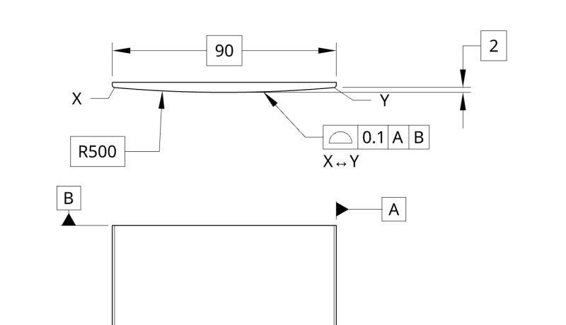
Hey, so I want to make sure I'm not incorrect. I've got a print that is similar to the above and it seems to me that the radius dimension could float from 499.95 to 500.05. The vertical dimension I don't see as necessarily having a tolerance, unless that would also be 1.95 to 2.05? I'm unsure on that one. I know that it's surfaces within that range, but thinking about it in limits of basic dimensions helps me visualize it.
However, the horizontal dimension, 90, shouldn't be basic, correct? It essentially has a tolerance of +/-0 since there's no GTOL related to this dimension from what I can see. For reference, I didn't create this print and I'm just trying to figure out what the person who drew it, who's no longer with the company, was thinking and ensure I'm not missing something obvious. Also the tolerance is crazy small for a part like this.
The main reason I ask all of this is because how this part was INSPECTED was with a radius of 500+/-0 and then the surface profile was taken separately with a tolerance of +0/-0.1. It should have been related to the 500 radius on the CMM, correct? Also the other two dimensions weren't inspected, but I'm still convinced that 90 shouldn't be basic, and I'm thinking that 2 shouldn't be either.
I'm looking to open the tolerance on this part, and what I THINK makes sense is to make the 90 a normal dimension, make the 2 a normal dimension, then make the profile tolerance something like 10. If I were to keep it how it is now and made the tolerance 10, that would make it 495 to 505 for the radius, but that would also make the 2 dimension range from -8 to 12 right? The 90 dimension would be unchanged from what I can tell.
I've been staring at this part for too long, so any help would be greatly appreciated. There are other dimensions on the print, but these are the only GTOLs on the print, and it just seems like a bad implementation of them to me. I hope I've made sense in my rambling.
