Continue to Site

Eng-Tips is the largest engineering community on the Internet

Intelligent Work Forums for Engineering Professionals

  • Congratulations cowski on being selected by the Eng-Tips community for having the most helpful posts in the forums last week. Way to Go!

profile tolerance

Status
Not open for further replies.

CanosSSCS

Mechanical
Sep 16, 2020
35
Hello,

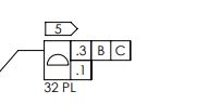
Could anyone provide insight as to how to read the profile call out below?

tolerance_call_out_-_eng-tips_sygxe3.jpg


thank you!
 
Replies continue below

Recommended for you

What standard are you adherent to?

Assuming PL is supposed to mean "places" and that this drawing is per ASME, although its not strictly an accepted Y14.5 pattern creation mechanism I would probably treat it the same as an "nX" pattern ie: the same as 32X (profile tolerance). That would probably be the most conservative way to interpret it anyway (more variation would be allowed if you didn't treat them as a pattern).

Or is the question about how to interpret a composite profile tolerance? In that case I would direct you to the pertinent portion of the standard (if Y14.5-2009 para 8.6/Y14.5-2018 para 11.6). The lower frame (0.1 - datumless) floats within the upper frame located/oriented to B and C (0.3 - B|C).
 
CanosSSCS,

That pointy box with the number 5 in it does not appear in the ASME Y14.5 standard anywhere. I have just checked everything from 1982 to 2018. Could this be ISO[ ]standard?

If I ignore that and apply ASME Y14.5 thinking, it makes sense. You have a shape that must be accurate to within 0.1[ ](millimetres?). The feature must be positioned and rotated to within 0.3[ ](millimetres?) with respect to datum features[ ]B and[ ]C.

--
JHG
 
drawoh,

I thought that little flag type box looked a little strange but I wasn't sure if I was the only one. My first guess was it is a designation for a note #5 which applied to the profile tolerance and is not shown in the snippet provided by OP. I could be wrong though.

Noticed after I read your response that my brain added datum feature A instead of just B|C to the upper frame, I corrected that.
 
chez311 said:
...

Noticed after I read your response that my brain added datum feature A instead of just B|C to the upper frame, I corrected that.

I did not notice you had done that. The primary datum ought to be in there. This indicates that the drawing has not been very well prepared.

--
JHG
 
Also notice that -- if it's following the Y14.5 standard -- the lack of a leading zero in front of the decimal indicates that this is using inches rather than mm.
Those are very generous tolerances; if they were intended to be metric then they should be 0.3 and 0.1.

John-Paul Belanger
Certified Sr. GD&T Professional
Geometric Learning Systems
 
OP here

The print calls out ASME Y14.5-2018. The number 5 is a note tag.
I am concerned about the units for the tolerances. The print states all dimensions are in mm unless otherwise specified, but if the annotation itself isn't correct (.1 vs 0.1) then i'll have a problem. I will revisit with the original drafter.

Thanks for the help!
 
For the units (and that bit about the leading zero), see paragraph 4.3.1.
Some may say it's pedantic to point that out, but it's worth keeping in mind if you have any voice in that drawing.

John-Paul Belanger
Certified Sr. GD&T Professional
Geometric Learning Systems
 
Status
Not open for further replies.

Part and Inventory Search

Sponsor