Eng-Tips is the largest engineering community on the Internet

Intelligent Work Forums for Engineering Professionals

Profile with all over and all around 1

Status
Not open for further replies.

Sa-Ro

Industrial
Jul 15, 2019
273
0
0
IN
Hi

Profile_with_all_over_jtcubg.jpg


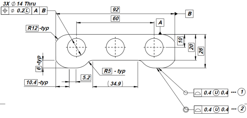
It is a aluminium extrusion part.

My requirement:

Manufacturing variation shall be within 0.4 mm disposed outside of the true geometry.

Option 1 (All Around): It will control the outer surface profile in the direction of symbol placed - 2 dimensional.

Option 2 (All Over): It will control all the outer surface profile - 3 dimensional. Will it control three holes size and location also?

Thank you.
 
Replies continue below

Recommended for you

The all-over profile may also be considered as applicable to the 3 holes unless you clearly state that it shouldn't, which shouldn't be a big of a deal for this simple geometry.

The all-round profile will not apply to the 3 holes, but it will also not control the front and back faces of the part.

Side note: As is, the position tolerance applied to the 3 holes does not control location of the pattern in the vertical direction, therefore another datum feature reference needs to be added to cover this.
 
pmarc said:
Side note: As is, the position tolerance applied to the 3 holes does not control location of the pattern in the vertical direction, therefore another datum feature reference needs to be added to cover this.

pmarc,
I think the same thing (control the location of the holes in the vertical direction) could be achieved if A|B| is added in the profile (all-around profile) callout. Am I corrcet in my assessment?
I want to say that no need for a standalone tertiary datum feature to control the vertical direction.
Do you see what I am saying?


greenimi,

I just realized that A on the drawing is the top flat surface, and not front or back face of the part, therefore my side comment doesn't really make sense.
 
Pmarc,
Let's pretend the primary is the top face or the bottom face. Then, I think, your side comment would have make sense, right?
Therefore, would my solution be valid or not?
 
greenimi,

I assume you are asking about changing A to the front or back face of the part in the provided view.

If so, then yes, my side note would make sense and your proposal to add A|B to the all-around or all-over profile callout would fully constrain location of the holes with respect to the contour in the vertical direction. The simultaneous requirements rule would do its job in that case.

But before doing so I would first ask myself if I truly wanted to control the two surfaces forming width B with respect to the datum center plane B established from that width. It's not that this would be illegal, it would just add additional, and possibly not needed, layer of complexity.
 
Since this is an extrusion, the tolerances should be on a per-length basis. The "All Over" callout should be removed and suitable controls for cut-off parts applied at that level of drawing unless it is the intention to control the saw cuts when the extrusion factory cuts them to length for shipping.

sa-ro_example2_pyvhe6.png
 
Pmarc said:
The all-over profile may also be considered as applicable to the 3 holes unless you clearly state that it shouldn't, which shouldn't be a big of a deal for this simple geometry.

How do I explicitly state that all over profile tolerance should not control the three holes?

3DDave said:
the tolerances should be on a per-length basis.

You mean flatness tolerance for 100 mm length and another flatness tolerance for 1000 mm length?

Thank you.
 
Hi Sa-Ro,

In a way, 3DDave is asking: Are you buying a "part", or are you buying bars of extruded material?

If you're buying material, talk to the extruder to see how they prefer tolerances to be specified. You might use notes to specify straightness per unit length and twist per unit length. Note: Here we're controlling the straightness and twist of the bars, not the shape of the extrusion.

To control the shape of the extrusion, I recommend the following, but some may disagree:

1. Use ONLY profile tolerances, either regular or all-around. You can use non-uniform profile tolerances to control of every portion of the shape independently.
2. Reference NO datums.
3. Explicitly indicate that all the profile tolerances must be satisfied SIMULTANEOUSLY.
4. Indicate the thickness of the slice of material that must satisfy the profile tolerances. If your particular application allows it, this means a convenient thin slice, like 10mm or something.
5. Check on an optical comparator with an overlay, or with a vision system, if you're fancy.

Side note: Be sure to carefully deburr your slices before checking them. Tumbling works great, but don't overdo it; it's easy to peen edges enough to alter their silhouette.


@Nescius

We are buying as a extrusion of 3 meters length.

Actual part vary from 100 mm to 600 mm length.

Our supplier requires flatness tolerance of 0.4 per 100 mm. No other tolerance for entire length.

My requirement is to control the shape of the profile within 0.4 mm.

Flatness at top and bottom shall be maintained 0.1 mm per 100 mm length and 1 mm per 1 meter.

If flatness increased to 0.4 mm per 100 mm, I need to add extra material and machining process.

Thank you.
 
Sa-Ro said:
We are buying as a extrusion of 3 meters length. Actual part vary from 100 mm to 600 mm length.
OK, you are buying bars of material. This is important. You are making a drawing for the extrusion supplier, and you probably do not care about the exact length of the bars. So, tolerances like all-over profile probably don't make sense here.

Sa-Ro said:
Our supplier requires flatness tolerance of 0.4 per 100 mm. No other tolerance for entire length.
Please clarify for me. How is your supplier using the term "flatness" here? Does it mean that a 100mm long piece of your extrusion will have flatness error of less than 0.4mm on the nominally flat areas?

Sa-Ro said:
My requirement is to control the shape of the profile within 0.4 mm.
OK, profile tolerances can do this very well.

Sa-Ro said:
Flatness at top and bottom shall be maintained 0.1 mm per 100 mm length and 1 mm per 1 meter.
This does not seem possible if the extrusion supplier requires a 0.4mm flatness tolerance per 100mm.

Sa-Ro said:
If flatness increased to 0.4 mm per 100 mm, I need to add extra material and machining process.
Yes. If I am understanding your situation correctly, your extruded bar stock will not meet the requirements of your parts.
 
Nescius said:
Please clarify for me.

Top and bottom surfaces are flatness 0.4 mm as per supplier requirement.

So that I provided profile tolerance with 0.4 outside disposed to maintain minimum size shall be as expected.

Thank you
 
Status
Not open for further replies.
Back
Top