Continue to Site

Eng-Tips is the largest engineering community on the Internet

Intelligent Work Forums for Engineering Professionals

  • Congratulations KootK on being selected by the Eng-Tips community for having the most helpful posts in the forums last week. Way to Go!

PROOF TEST FOR PIPE BEND (ASME B16.9) 2

Status
Not open for further replies.

Ilanseran Ramadass

Mechanical
Feb 3, 2023
24

Hello

Am in need of performing proof test for the Pipe Bend.

As per ASME B16.9 Clause 9.3, we are arriving a proof test pressure of 79.6 Mpa.

Test Specimen Specification:

OD of pipe bend - 323.8mm
Thk of pipe bend - 25.4 mm
Ultimate tensile strength as per MTC -483.24 Mpa

We will be assembling the pipe bend with both end connected with the straight pipes with End plate.

I performed the Straight pipe & end plate strength calculation by the attached document(Excel file). But It seems to be fail. Can anyone elaborate this proof test concept & please conclude whether my Excel calculation is correct....

Thanks in advance
 
 https://files.engineering.com/getfile.aspx?folder=4f3356f1-72c4-4e94-8b9b-5a6368164c08&file=Hydro_test_-_End_plate.xls
Replies continue below

Recommended for you

That is some mother of a pipe and pressure.

ASME what? ASME VIII or some other code?
What is IBR? why does it only use 40% of the yield stress?

What is the design pressure?
How did you calculate 79.6 MPa for the test pressure?
what has the UTS got to do with it?

Why are you even doing this as opposed to just testing the entire spool or fabrication?

Can't you use flanges? Have you even thought about how you are going to weld on a steel plate 100 mm thick onto a pipe with wt of 25mm? did you no think this was a bit odd?

Basically I tried and for the test pressure and using the A106 grade B, and 90% yield you need nearly 60 mm for this pressure ( 800 bar).

Please go away and look more closely at your design inputs then come back to us.


Remember - More details = better answers
Also: If you get a response it's polite to respond to it.
 
Hello Mr. Little Inch

Thanks for your valuable reply

We are proceeding this Proof test as per ASME B16.9.

Since, we presume that Pipe bend is a wrought Fitting as per ASME B16.9 Clause-5.

Find my reply for your Questions:

What is the design pressure? - Design pressure not needed for this case as we are performing Proof test, we require test pressure only
How did you calculate 79.6 MPa for the test pressure? - As per ASME B16.9 Clause-9.3
what has the UTS got to do with it?- Pls refer ASME B16.9 Clause-9.3

100mm plate weld with pipe is possible only, but the only disadvantage it requires lot of time & cost. As it is an one time test cost does not affect it.

One doubt Mr. Little inch, 60mm thickness is for straight pipe or for end plate that you had mentioned?

Thanks

 
Ah, OK this is a proof test to near rupture of a new bend making procedure?

Your issue is that the weakest part of the system needs to be the bend itself.

But if you use the same material and same thickness for the pipe identical to the elbow / bend, this pipe section could burst first before you get to the min proof pressure or yield so much that it causes the test to fail

IMHO, the pipe should be designed so that at the proof test pressure, it does not exceed 90% of its SMYS.

So you can either increase the thickness of the pipe or increase the strength of the pipe.
For the former using A105, I calculated for thickness this was nearly 60mm thick, so I suggest you use pipe like 5L X65 or X70 and a thinner thickness.

Remember - More details = better answers
Also: If you get a response it's polite to respond to it.
 
Hello Mr. Little Inch,

I had a small doubt in your statement that, straight Pipe will burst first before the pipe bend before it reaches the Min proof test pressure if we are using same material & thickness for pipe & pipe bend.

My doubt is that pipe bend will have some thinning allowance, so that pipe bend will be the weaker one compared to straight pipe.

Can you please explain the background that how the straight pipe will burst first?

Thanks in advance.

Kind Regards,
R.Ilanseran
 
Ramadass,

I said the straight pipe COULD fail.

Looking back I am not sure what it is you are testing. You keep calling it a bend, but B16.9 is specifically for "wrought" fittings, normally called elbows.

Is this an induction bend made by heating and then bending straight pipe?
what radius is this "bend"?

Usually the pipe for bends is made thicker than the connecting pipe to allow for bend thinning, but this is NOT a ASME B 16.9 bend.

There are many unanswered questions.
Please review the previous posts and answer the questions and then we might get somewhere.

Remember - More details = better answers
Also: If you get a response it's polite to respond to it.
 
Hello Mr. Little Inch,

Regret for the Inconvenience.

Yes, this bend is produced by the Hot induction bending machine (Heated first & then pipe bend will be done).

Actually we need to prove that our bending machine is capable for making pipe bend for the client. They are asking us to make a proof test for pipe bend. That's why we gone ahead with ASME B16.9 , Although it calls for Wrought fittings like elbow etc..

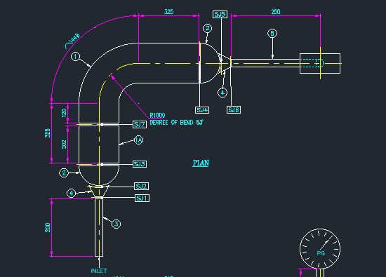
Pipe used for pipe bend is 300DN X 21.44 Thk (Bend radius =1000mm) & straight pipe at both end of pipe bend is 300DN X 21.44 thk

Proof test assembly is attached here for your easy reference

Thanks in advance.

proof-2_xmseln.jpg
proof-1_ftt8my.jpg


Kind Regards,
R. Ilanseran
 
Your first post said thickness 25.4mm, now it's 21.4mm - which one?

Your calculation appears to ignore the bend thinning. BS POD 8010 calculates this to be 12.5%.

SO I get a B16.9 test pressure to be about 600 bar based on a start pipe wt of 21.4mm, depending on what test factor you are using.

Don't understand why you don't just UT the bend after manufacture and take a load of hardness tests which are usually the critical thing for this type of bend.

This test does nothing for you or your client in my opinion in terms of knowing if your machine can do this. Many other factors at play here.

If you do it make sure you have a lot of concrete around it to avoid creating a serious risk to people. If 600 odd bar goes you could easily end up with bits flying off. Or very high velocity water jet.


Remember - More details = better answers
Also: If you get a response it's polite to respond to it.
 
The B16.9 test is at the measured UTS so it's a burst test. Not sure what happens of it breaks before the test pressure.

Ask a bit odd if you ask me.

Remember - More details = better answers
Also: If you get a response it's polite to respond to it.
 
Well, I don't understand why the calculations in the spreadsheet have a cylinder allowable stress of Yield. The connected cylinder has a calculated stress of UTS at the test pressure.
This is because the cylinder and elbow will have similar burst pressure if they are the same thickness.
If the cylinder and elbow have the same thickness, and the cylindrical pipe bursts before the elbow, then this is good. Just give the elbow the same rating as the connected pipe.
If my memory is right, this is how the philosophy of B16.9 works. (i.e. make sure the fitting bursts at a higher pressure than the connecting pipe, and then give it a pressure rating of the connecting pipe)
 
The calculation is wrong: UTS is 4218 kg/cm2 (60,000 psi). You need to use actual UTS from the material test report, may be over 4218 kg/cm2.

This is not a burst test, it is a design proof test.

Regards
 
Status
Not open for further replies.

Part and Inventory Search

Sponsor