Continue to Site

Eng-Tips is the largest engineering community on the Internet

Intelligent Work Forums for Engineering Professionals

  • Congratulations IDS on being selected by the Eng-Tips community for having the most helpful posts in the forums last week. Way to Go!

Propeller Pitch Distribution

Status
Not open for further replies.

TugboatEng

Marine/Ocean
Nov 1, 2015
11,556
My application isn't a pump but it's similar. Propeller on my boats are distributed pitch props in nozzles. I am having an issue where the low speed load from the prop is too high. Typically to reduce load, one would re-pitch the prop but that would also reduce the high speed thrust. This is a varying pitch prop so it has more pitch towards the hub and less towards the tips. Am I wrong to think that increasing pitch towards the hub while simultaneously reducing pitch at the outer diameter would, maybe, decrease thrust at low rpm and maintain it at high rpm?
 
Replies continue below

Recommended for you

Actually, there are slip rated clutches for these drives. Thanks for the idea.
 
I don't have any experience with them but does anyone have any thoughts on a torque converter?
 
OP,
Concerning the amount of air required. I am really swagging this because I don't have good feel for prop dynamics.
So, I see a low-speed prop rotating around ~20rpm, I also imagine the blades average area to be around 2' wide in the axial direction. So, the volume of the blade would be 10' diameter, 2' deep, with 4 blades, the swept volume would be ~600ft3, at 20 rpm that 12000 cfm. Since we are at low velocity a reduction in velocity or mass should have about the same effect. For a 1% loss, you would need to displace 120 cfm of water. Assuming a 20' draft, you would need to supply ~200 cfm of air. You should be able to extrapolate this linearly across the lower rpm ranges but as you increase velocity, the mass displacement starts to lose to velocity. There should be additional losses in both kinetic energy and momentum transfers due to the entrained air, but I don't have a good feel as to how to swag those. I may be way off, and I apologize if I made ignorant assumptions, but it made sense in my little squirrel brain.
 
OP,
A torque converter would add loss to the drive train throughout the rpm range even though the losses should be less at higher rpms. From what you are describing, you need slippage at low rpms and direct coupling at higher rpms, the only way that comes to mind, to perform that function mechanically, would be with a clutch.
 
So, between 86-163 would be where you are having issues. I know prop theory is a field of its own and my method is not accurate or correct, but my toolbox is limited. That said from an order of magnitude perspective, it might get you close enough for testing. Based on a swag, you are looking at between 500-1500 cfm but could be less. I am thinking a bollard pull with an air compressor on deck with hose securely fasten to the z-drive mast. Run it through the rpm ranges and see if it makes a difference. This is not a typical engineered solution and if you think its worthless then it likely is. The only reason I am bringing it up, is it sounds like you're looking for way to remediate an unforeseen issue due to detuned engines that's a quick achievable fix, so I am throwing out down and dirty ideas I typically wouldn't.
Another down and dirty idea.....Typically adding back pressure to a turbodiesel leads to decreases efficiency and performance. To meet emission requirements, it sounds like the engine manufacture detuned their ECM. I don't know how the ECM will react to increase in back pressure but if you could temporarily increase back pressure the ECM might try to overcompensate to get you through the existing underpowered rpm range. Warrantee issues, your emission requirements, company policies....No idea if this is possible or recommended or just a bad idea but I'd thought I'd though it out.
 
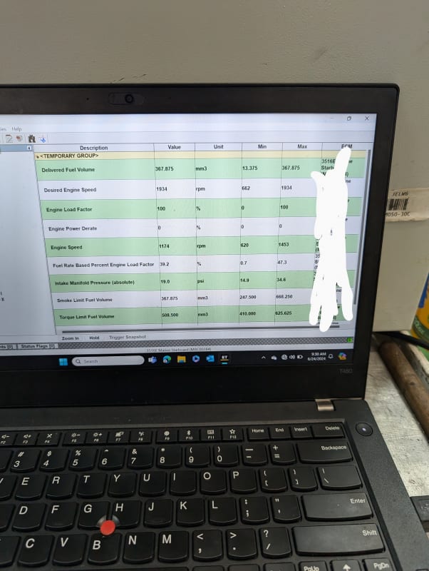
It's an electronic limit based on boost pressure. You can see the smoke limit fuel volume and delivered fuel volume are equal, the engine will not fuel more.

PXL_20240624_163018260_2_xtmrhl.jpg
 
Is the speed reduction internal to the z-drive or is there as sperate transmission for this purpose? Is it a fixed ratio? (it appeared to be based on the prop and rpm numbers you provided) I am wondering if a different prop and speed reduction could shift the prop curve's low end slightly lower while still reaching the max prop / engine output intersection.
Also,
Are you trying to avoid dry dock solutions or is that a concern at his point?
 
The speed reduction of 7.5:1 is entirely within the Z-drive unit. I am first, trying to avoid out of service time, second trying to avoid dry docking, third trying to avoid buying new props and nozzles.
 
Assuming you are using a proprietary Cat engine monitoring software. Considered any aftermarket ECMs, and a more generic engine management software used?
 
I have a workaround but will not implement it due to prison risk.
 
Understandable, I was going to ask if end users were required to maintain tier 4 requirements or if it was only the engine manufactures, but you indirectly answered my question. Related to my last question, I am assuming all E3516E's have like ECM tuning. I was wondering if there are aftermarket companies that can provide a more specific tune to your needs while still maintaining Tier 4 requirements and certifications.
 
The problem is that there are only two companies that make high speed diesel engines in this power range and there are very few customers that need tier 4 engines. There is not much interest in us.
 
EPA T4 is the strictest standard by far.

On a side note, railroad engines are mostly Tier 2 and older. The railroad has a very powerful lobby that has protected them. Recently, California decided to enforce tier 4 in them and they're having a tantrum.
 
All propellers have a flatter pitch at higher radii, steeper pitch at shorter radii. I thought the idea is to get as close to moving the fluid through the prop at all radii at an equal velocity for any given speed. If you don't do that, you'd be creating vortices along the longitudinal axis of the blades. Circulation from propeller axis to tip. That doesn't sound like a good idea.

So controllable variable pitch marine propellers are out of the question?

Now I'll read all the thread to see if that has been discussed.

LittleInch was talking about uniform velocities in the propellers sweep. Messing with changing pitch at certain radii... doesn't sound like you'd want to do that.

--Einstein gave the same test to students every year. When asked why he would do something like that, "Because the answers had changed."
 
Might be worth a call to Black Dog Propellers or someone else who has Prop Scan to see if they can improve the design.
 
Status
Not open for further replies.

Part and Inventory Search

Sponsor