Eng-Tips is the largest engineering community on the Internet

Intelligent Work Forums for Engineering Professionals

Proper GD&T for interrupted threads?

ericscottf

Mechanical
Oct 15, 2024
4
0
0
US
Hi all,

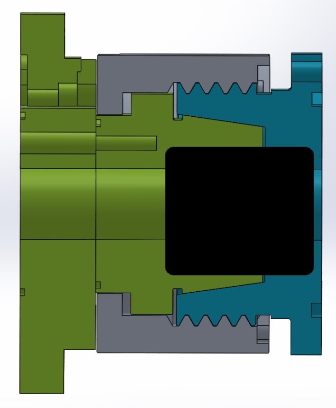
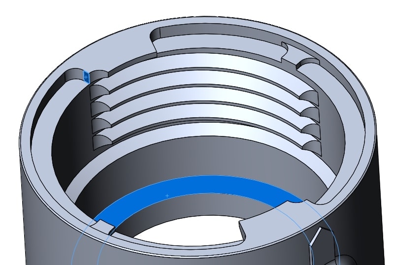
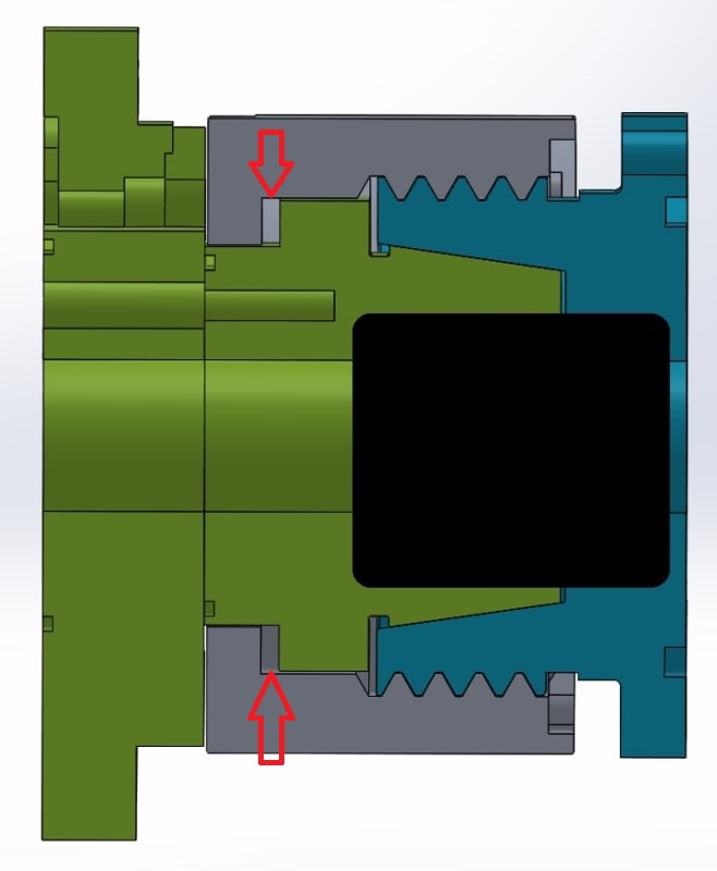
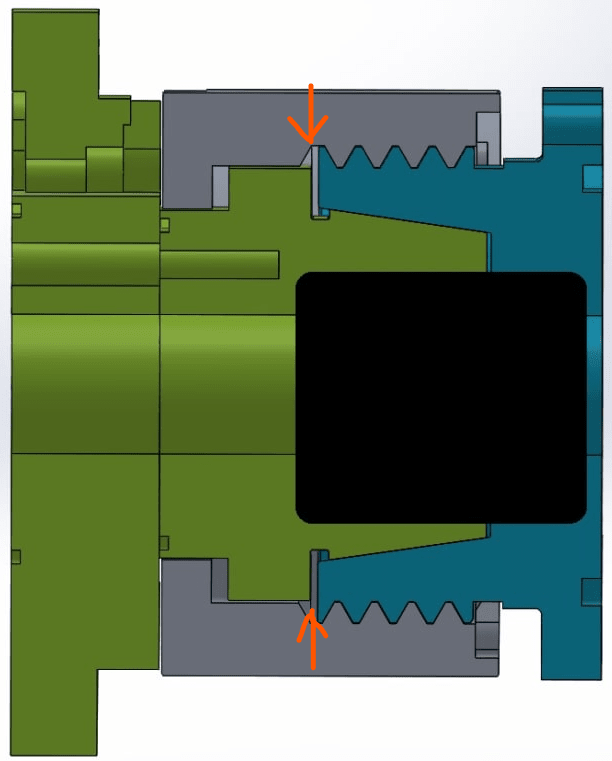
I am working on a connector design that uses interrupted threads (M39x3.0) to allow for a quarter-turn lock. It is a 3-part design where the mating surfaces have to come to within 0.004" when all stacks up. 1 part has internal threads, 1 part has external threads, and the middle part is between them and gets clamped by the mating threads.

We'll be making 1000s of these over many years, and the parts from the first run must properly mater with parts made at a different mfr years later. Therefore, I must figure out a way to tolerance the thread position, start, etc, to an accuracy that will allow for such a mate.

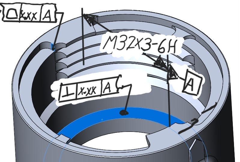
It is clear to me that I'll be detailing each part on its own, threads to important surfaces, not detailing across the assembly (except maybe as a note in order to provide clarity)

In my 22 years of machine tool design, automation and robotics R&D, I have never come across a need to do such a thing, nor has Google helped me find an elegant solution to this.
I could cobble together some planes, surfaces, and such, and draw this up in such a way to be correct... but possibly overly complicated and difficult to understand. I could also detail out the requirements in notes, but I'm confident that would not result in proper mating across different manufacturers/years apart.

Does anyone have any references/tips to provide as far as detailing such parts? I'm certain this has to be a thing, as there are plenty of parts like this in the automotive industry, where such detailing would absolutely be required.

Thank you!
 
Replies continue below

Recommended for you

Could you post some rough sketch of the parts in question, how they mate, and what specific geometric relationships between features you want to control to ensure the fit?
 
Blacked out some of it... Here's the idea. For the grey part, I care about the 2 blue surfaces (one is tiny) to the threads themselves, both radially and axially.
I can create planes/offsets/etc to cobble together the info necessary to produce the right result, but I'm wondering if there's a "proper" way to handle this.
Note that the 2 sections of threads are rotationally symmetrical - this is not a continuous thread, it would be considered a double start thread, except for the fact that the pitch of the thread won't support that profile if it were continuous.

screw1_hr9dsm.jpg
screw2_oc5azp.jpg
 
Hi, ericscottf:

Are you familiar with ISO GPS or ASME GD&T? If you are, you need to show your proposal. Then we can do critics.

Best regards,

Alex
 
If using ASME Y14.5, The ugly way is to use a profile tolerances on the thread surfaces relative to the flat mating surface as primary and clocked to the tiny stop as tertiary, as well as some secondary diameter as a reference for location.

Instead of specifying the thread per any thread standard, use the nominal definition to supply a basic dimensioning scheme and apply an appropriate tolerance. The non-mating surfaces can have a larger tolerance and more clearance, in keeping with maintaining enough thread section to be sturdy enough for the task.
 
It looks to me like the taper between Green and Blue, or the shim/washer/??? shown in the cross-section will have a race to control the draw-up. So it's not clear to me why the threads need to be super precise.

In my experience designs that "will be perfect, if we can just hold the tolerances tight enough" never work out.
 
It's not just the draw-up - it is that the partial threads need to engage the other partial threads nearly completely in rotation about the thread axis at the time there is tension on the threads.

Often this is done by using a wave spring to make up the difference, but that's not always an option.

I don't know what the olive green part does, but it doesn't look like anything keeps the conical(?) surface on it engaged. The split line in that same part is a bit head scratching as well.

I's guess that is the disengaged position except the teeth/screw thread appears to be engaged - which is what the old fashioned section lines would make clear, that solid shade slices doesn't.
 
Possibly a component that was hidden by the black portion gets sandwitched and clamped between the blue and green parts, and then there must be gaps maintained between the green and blue cones and between what may be a washer and the end face of the blue part, in the fully tightened condition.

What does the small flat face lighted in blue on the grey part do? Is it used somehow to lock the grey and blue parts in rotation to each other at some point to prevent the blue from getting completely detached by untightening the threads?
 
For handling the interrupted threads and their starts I would expect some kind of functional go-gage implemented, considering the expected quantities and long-term production.
 
Indeed there is a spring (urethane ring) between the grey part and green part that is to take up the slack in tolerance and provide axial force to lock the tapers together Shown by the red arrows in the attached drawing.

The split between the two green parts is to allow for assembly. The grey part spins to engage/disengage the threads, and as it disengages, it pushes on the green part on the left, which will break the taper apart. The taper is a 7:24 taper, like an ISO30 tool taper, meant for load capacity and also release capability, however they do sometimes lock up, so an assisted break is desired.

The small flat face highlighted in blue on the grey part hits a stop pin that's pressed into the blue part (there's actually 2 of them 180 apart). This stops the rotation at the appropriate maximum engagement point. it is at this point that the threads have complete overlap, and the urethane spring has "just about the right amount" of compression on it to provide the axial force to lock the parts together.

The black box is covering the circuit boards/electrical contacts/engagement mechanism for them, not necessary for this query and non-trivial enough to where I do not want to publicize it.

I've discussed with the team and they are "OK" with having master parts made that will be used by any mfr that we sub this out to in order to gage the parts. This is not how I would like to proceed, but it does make my life easier as far as this goes. I'd still like to know how to properly dimension these threads with proper technique, just for the sake of knowing something new that I will likely never need to use again (my favorite kind of knowledge)

screw1_hr9dsm_evltal.jpg
 
As I wrote - use profile of surface to control the threads relative to the other surfaces. Since the cone is the primary surface that stops axial motion and two degrees of rotation and two degrees of translation, that looks like the best candidate for this use. The stops would be the secondary control.
 
Back
Top