ericscottf
Mechanical
- Oct 15, 2024
- 4
Hi all,
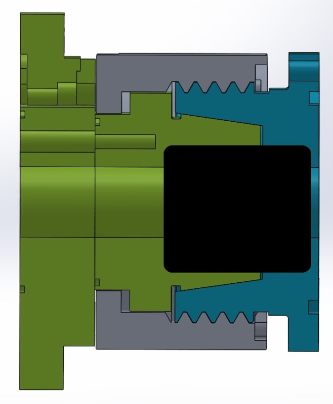
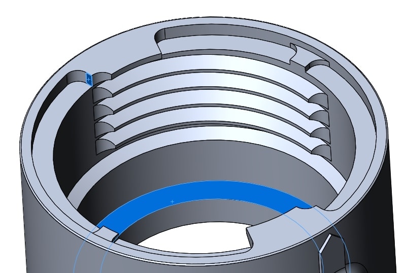
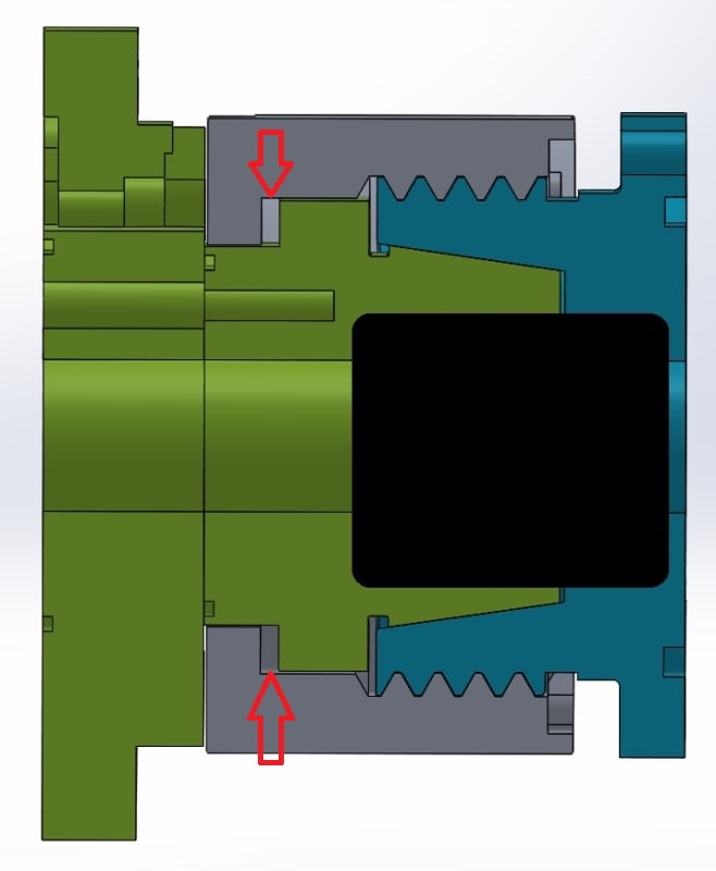
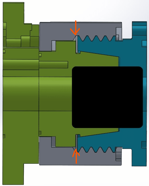
I am working on a connector design that uses interrupted threads (M39x3.0) to allow for a quarter-turn lock. It is a 3-part design where the mating surfaces have to come to within 0.004" when all stacks up. 1 part has internal threads, 1 part has external threads, and the middle part is between them and gets clamped by the mating threads.
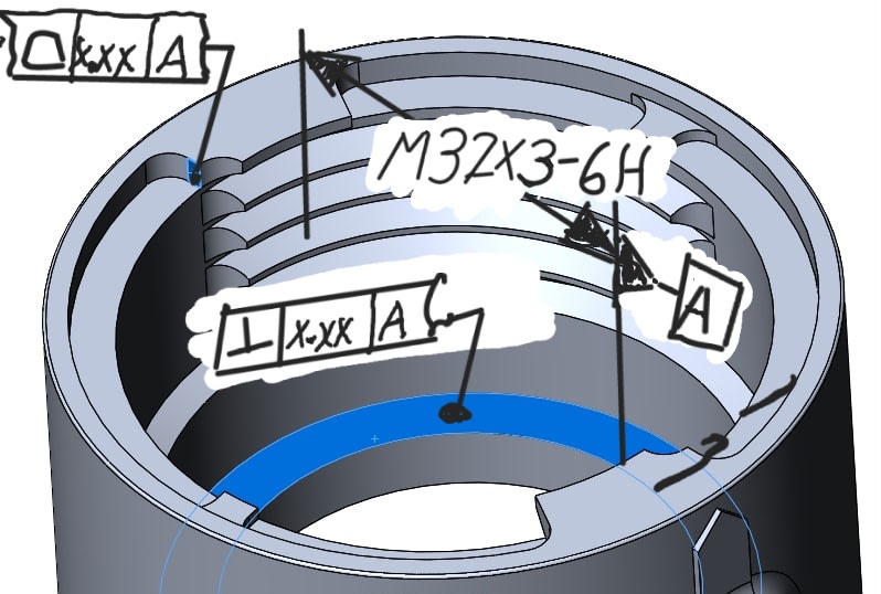
We'll be making 1000s of these over many years, and the parts from the first run must properly mater with parts made at a different mfr years later. Therefore, I must figure out a way to tolerance the thread position, start, etc, to an accuracy that will allow for such a mate.
It is clear to me that I'll be detailing each part on its own, threads to important surfaces, not detailing across the assembly (except maybe as a note in order to provide clarity)
In my 22 years of machine tool design, automation and robotics R&D, I have never come across a need to do such a thing, nor has Google helped me find an elegant solution to this.
I could cobble together some planes, surfaces, and such, and draw this up in such a way to be correct... but possibly overly complicated and difficult to understand. I could also detail out the requirements in notes, but I'm confident that would not result in proper mating across different manufacturers/years apart.
Does anyone have any references/tips to provide as far as detailing such parts? I'm certain this has to be a thing, as there are plenty of parts like this in the automotive industry, where such detailing would absolutely be required.
Thank you!

