Continue to Site

Eng-Tips is the largest engineering community on the Internet

Intelligent Work Forums for Engineering Professionals

  • Congratulations SSS148 on being selected by the Eng-Tips community for having the most helpful posts in the forums last week. Way to Go!

Proportioning a girder in an old drawing

Status
Not open for further replies.

tmalik3156

Structural
Jun 21, 2021
106
Bridge_mnopr0.png


Hello all,
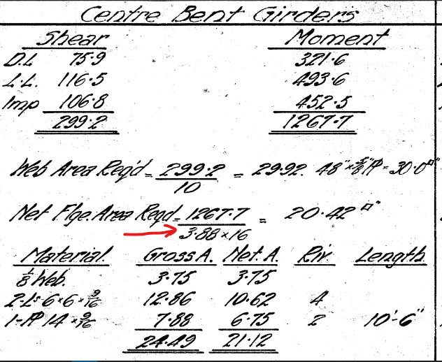
Attached is the calculation of proportioning a girder of an old bridge.
Can someone help me in understanding what this 3.88 is?

Let me explain in detail. In those days, the yield strength of structural steel was 29 ksi.
So, the allowable stress in shear was 0.35Fy = 10 ksi, and in bending 0.55Fy = 16 ksi.

As you can see, they calculated the shear load of 299.2 kip, and then divided by 10 ksi to get the required web area which is 48 inch by 5/8 inch. This is easy to understand.

But then to get the flange area, they are dividing the moment by 16 ksi, and also by 3.88 to get a flange area of 20.42 sq inch.
Then they use one-eighth of the web plus double angles plus a plate to get the required area.

I wonder what this 3.88 is! Can anyone figure out?
 
Replies continue below

Recommended for you

I think it is 3.88 feet.

I assume the 1267.7 moment is in kip-ft, so dividing by the distance between flanges (I assume 3.88 feet) would give you the flange force.

Then dividing the flange force by 16 (ksi) gives you the required area.
 
@ gusmurr,
Thank you. Yes the unit has to be of length (feet), and it's likely a moment arm.
However, this is a strange way to proportion the girder. Usually, when we know the moment demand, and the allowable stress, we get the required section modulus (S = M / Delta_allow). Then we proportion the flange.
Here they seem to be assuming that stress remains constant over the depth of the flange. But surely stress varies linearly.
 
The designer calculated the centroid of the flange (plate, angles, and 1/8 web depth) about the extreme edge of the flange; multiplied by 2, and substracted it from the overall depth. I learned the same method in college back in the 70's, except we used web depth/6 instead of 8. The 6 gives a slightly larger flange.
 
@ bridgebuster. Thank you very much.
This is a 1924 bridge, so perhaps they were more conservative in taking smaller web depth.
By the way, this method seems to assume that stress is constant over the flange. But surely, if the tip of the flange has attained 16 ksi allowable, then at the centroid of the flange, and at the bottom (1/8 web depth) the stress is smaller, as stress reduces linearly in allowable stress design.
 
I assume this was used for preliminary sizing of the girder, and not as final design or capacity check, although it's possible that this is the complete design of the girder for vertical load. Given the rough approximations of the load effects, and the significant variations in the material properties, the lack of refinement in calculating the section properties and stresses is not surprising.

That said, the variation in stress through the thickness of the flange of a rolled beam or plate girder would be very small. In this case, this is a built-up girder, so there is no direct connection from the web to the flange. The forces flow through the riveted connections between the web and the angles, and the from the angle to the flange, so the variation of the stress within the flange plate is very near zero. Also, you'll notice more than half of the area included as part of the 'flange' is actually the 6x6 angles.

Rod Smith, P.E., The artist formerly known as HotRod10
 
Allowable stress doesn't mean elastic stress. A simple way to proportion a girder for bending, used also nowadays, is to use the plastic capacity of the flanges and the moment arm formed between flange centroids, which seems to be what this early 20th-century designer did. If you consider that the web also carries some bending (say, 10-20%, depending on proportions of web and flanges) and that the Bernoulli hypothesis is not an exact representation of reality (linear stress variation is just an idealization and it applies at the length-scale of the beam cross-section), the reasoning is sound.
 
Status
Not open for further replies.

Part and Inventory Search

Sponsor