Continue to Site

Eng-Tips is the largest engineering community on the Internet

Intelligent Work Forums for Engineering Professionals

  • Congratulations SSS148 on being selected by the Eng-Tips community for having the most helpful posts in the forums last week. Way to Go!

Propping of Old Cast Iron Columns for New Foundation? Advice on Methdology?

Status
Not open for further replies.

gmannix1000

Structural
Dec 6, 2010
21
Hi All,

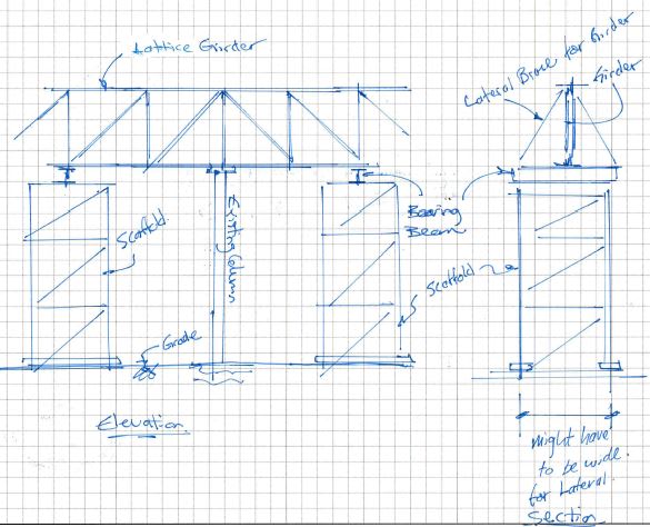
Looking for peoples thoughts on this - I have a line of existing cast iron column needing to be retaining on site but existing crap foundations need to be removed and replaced by new structure. The line of columns only hold a lattice girder, unloaded, just carrying it's own self weight. Three existing columns are circular, two are channels with plates connecting them vertically at 1200c/c and one column is a I section with rivits through both sides of the flanges. See attached. Note we are trying not to bolt through or cut any existing steel because we're concerned of the ductility of the cast iron. Columns are about 5m high. Cast-iron column will become a tension column with its own self weight in the temporary case until it is supported by new structure shortly after.

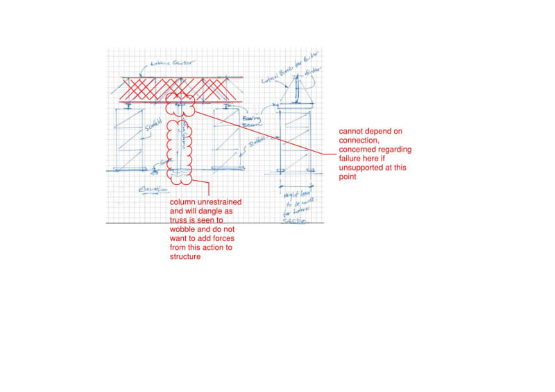
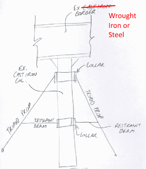
To do this, I came up with a tripod propping system, attached to the underside of the lattice girder around the truss via a temporary collar clamped tight around it and propped securely to a ground embedded pad foundation. The tripod props will carry the dead load of the girder and keep the truss from moving at the top. I have another collar mid-height of the column with a tie restraint beam back to the props to stop the column dangling and potential girder rotation once the existing foundation is cut out and removed. See attached. Does anyone have any advice or encountered any similar situation or should I specify any other safe measures?

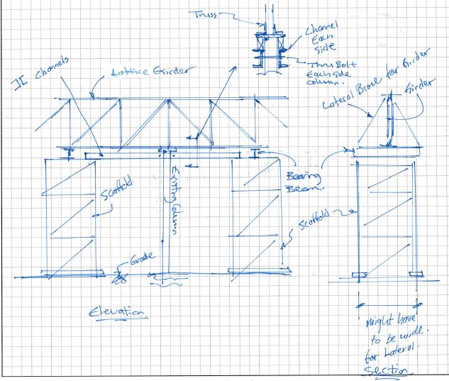
So this works for the circular cast iron columns but for the other two, I'm stumped. Anyone any ideas how I can collar/clamp to an I section with rivits and a column made up of two channels/vertical plates @1200 centres and rivits? See attached. Have to clamp/support the column at the top to stop lattice girder moving and trying to avoid drilling.

Any comments gratefully appreciated!
 
 https://files.engineering.com/getfile.aspx?folder=ce46b99c-8eed-40cd-a7ad-b6c3d334009c&file=Existing_Columns_Prop.pdf
Replies continue below

Recommended for you

Any reason you can't just put in temporary columns, offset from the existing enough to get in the new foundations? Changes the support conditions of the truss, but if its just holding its own self-weight that shouldn't be an issue.

I think your current detail is unnecessarily complicated. Not saying it couldn't be made to work - but a few shoring posts (or shoring towers made of scaffold) would be much simpler, with much less potential for things to go wrong.
 
The existing columns and lattice girder has no lateral restraint at the moment until the building is in and has been noticed to wobble currently in high winds. Straps are keeping it from swaying at the moment so even if I prop the girder, I still have no rigidity from keeping this thing from swaying while we're cutting out the existing foundations and replacing new ones under a dangling column (which would rotate the girder further - does this make sense?
 
gmannix1000 said:
Three existing columns are circular
...two are channels with plates connecting them vertically at 1200c/c
...one column is a I section with rivets through both sides of the flanges.

Cast-iron column will become a tension column with its own self weight in the temporary case until it is supported by new structure shortly after.

Cast-Iron-Column-300_dzxjdd.png


First the girders, depending on when manufactured, they are almost guaranteed to be either wrought iron or steel.
(Nineteenth century engineers were not naive. Cast iron was not used for beams or girders since part of a loaded beam will be in tension.)

Before 1890, probably wrought iron.
1890 to 1895, either wrought iron or steel.
1896 or later, probably steel.

Now the columns, cast iron columns were used well into the 20th century and were always somewhat unpredictable... therefore conservative loading was used.
The two columns made from channels and plates plus the one column made from and I section... wrought iron or steel, not cast iron. (see above).

Be very careful (personnel safety) with the cast iron columns while they are temporarily hanging (with no imposed load).

Agree with CANPRO, the plan is way too complex.


[idea]
 
I am assuming you are not dismantling it because rivets or welds were used for attachment of the parts, not bolts.
I agree with Canpro, brace/support the beams.
 
gmannix1000, see sketch below. Its easier to not rely on the column. I don't know what your loads are like, but you could likely do this with scaffold and a bit of custom steel for directly supporting the truss and bracing it laterally.


Girder_shoring_oxo8aa.jpg
 
Hi CANPRO,

Thanks for that. Ideally, I would like to have done this. The lattice girder is in poor condition and many diagonals are missing as it is - 'hanging' the column from this is concerning and preventing the column from dangling or dropping away from the truss is the other concern.

Document1_ojprev.jpg


I suppose we're just trying to mitigate any concerns with the tripod propping...
 
I guess I don't fully understand what you're intentions are. If you're putting a new footing under the column, I'm assuming you're putting the column and girder truss back into service. Won't the diagonals have to be fixed? And if you're missing diagonals near the column, even more reason not to support it from the column. If you put shoring towers either side, you can isolate the locations of the truss that are structurally deficient.

If you can't have the column suspended, that obviously needs to be addressed, but it doesn't have to complicate your shoring - which also needs to be done safely. See below for revised sketch - its rough, trying to eat breakfast at the same time.

Run a channel each side of column, spanning between shoring towers. Add a thru-bolt each side of column to wedge the column between the channels. Provide blocking tight to the underside of the column cap plate.

Girder_shoring_udpmgt.jpg
 
Build CanPro's scaffolds, add a collar close to middle of round column, span 2 small beams between scaffolds but under the collar, adjust 2 beams up to take weight of column and trap movement by adding 2 cross members between beams.
 
Canpro's suggestion is a typical method when renovating bridge girders at least for the company that I used to work for.
 
Gmannix1000:
You could use SRE’s, 17APR19, 21:19, tripod scheme, with three or four legs, and with collars near the top and another lower on the column, as a tension ring, maybe near the column base. Be careful with the cast iron columns, it seems to me that I’ve seen instances where they were cast in several pieces, a capital, a shaft, and a base, more or less just sitting atop each other. What are the column loads, lengths, etc., more of the needed engineering info. and design details? My upper compression collar has some added features: tension rods running down the sides of the column at each leg and with nuts and washers above the collar for tightening the rods up. The rods may have a turnbuckle down near the column base, and they have a bracket with an “L” shape, with the horiz. fingers going under the col. base to hold it up and together. The vert. leg of the “L” shape is attached to the tension rod and long enough to accommodate some eccentric loading btwn. the rod tension and the horiz. finger load, maybe reacting with the lower collar/tension ring.
 
dhengr said:
You could use SRE’s, 17APR19, 21:19, tripod scheme...

That is the OP's sketch, not mine. In fact,I do not recommend that approach, and said so. My reason is the same as yours. IMHO, cast iron columns used for structural reasons are potentially dangerous (brittle failure). They were when new and a certainly that way today.

[idea]
 
Consider the cast iron columns as a valuable antique, but not a primary structural member. Insert a new circular column inside the old member and have it carry part of the load. you can have the new vertical auxiliary support assume part of the load by a screwjack or ram under the inner column. Doesn't need to assume the whole load, merely enough to reduce the catastrophe if the cast iron shatters.
 
Status
Not open for further replies.

Part and Inventory Search

Sponsor