Continue to Site

Eng-Tips is the largest engineering community on the Internet

Intelligent Work Forums for Engineering Professionals

  • Congratulations GregLocock on being selected by the Eng-Tips community for having the most helpful posts in the forums last week. Way to Go!

Pump in parallel - Fluctuations in flow 1

Status
Not open for further replies.

Liad

Chemical
Feb 25, 2021
15
Hey all,
We are running a system with 3 positive gear pumps in parallel that installed at the outlet of a tank, like the picture below:
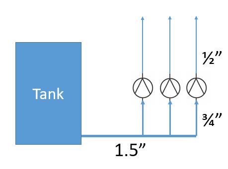
Capture_frwoz5.jpg

The left pump is the closest pump to the tank.

The outlet of the tank is 1.5", going up to suction of the pump is 3/4" for each pump and the discharge pipe is 1/2".
On each pipe coming out of the pump we installed an very accurate mass flow meter.

We are facing an issue when we are working in 2 or 3 pumps. when running a single pump the flow is stable.
When working with two pumps, the pump that closer to the tank having fluctuations in flow, while the pump that is further away has a very stable flow.
When we are working with 3 pumps, the pump that closest to the tank has fluctuations and the other 2 are very stable.
The flow is the same in one/two or three pumps.

I would be happy for your opinion on the subject, I assume that the reason is losses in head suction, but from calculations I have made there should be no problems.
Thanks in advance.
 
Replies continue below

Recommended for you

Liad,

Can you advise what the velocities are with 1,2 and 3 pumps in the inlet line?

If these are gears pumps what do you mean when you say "The flow is the same in one/two or three pumps." Flow in total or flow through each pump?

What is the fluid and its viscosity / vapour pressure?

What is the tank level?

What are the lengths here?

It sounds / looks like pump 1 on the left is being starved of fluid and possibly either cavitating or if there is more flow you are drawing in air which is going primarily to pump 1

Have you tried swapping the pumps around to see if the issue is the pump or the location?

Remember - More details = better answers
Also: If you get a response it's polite to respond to it.
 
The flow across the nearest branch is interfering with the flow into that branch. It is a turbulence issue.
Build a new manifold, use 2" and use 45deg tees for the takeoffs.
In some cases you see this with sensitive pressure gauges.
We used to install differential gauges with the reference being in the tank at the same height as the outlet, and the sense line being mid-way down each branch. Those gauges were sensitive enough to show the fluctuations.

= = = = = = = = = = = = = = = = = = = =
P.E. Metallurgy, consulting work welcomed
 
It is obvious that the suction piping does have the capacity required. What is the fluid and its viscosity and vapor pressure? What fluid are you pumping?

If the suction piping diameter was increased, the problem will go away. Don't believe you need 450 tees.
 
Mass flow meters are very sensitive to bubbles. Bubbles are probably getting into the pipe and going up the first branch.
 
It could be a whole pile of things. As usual we have 10% of the required data to even start making educated guesses....

Remember - More details = better answers
Also: If you get a response it's polite to respond to it.
 
I have worked with headers that were easily twice the required size and had issues where the flow past a branch disturbed the flow in that branch enough to starve a pump inlet.
Yes, there are a lot of other things to rule out first.
But fluids don't make 90deg turns, a change in momentum has to involve a change in flow and pressure. Nothing comes free.

= = = = = = = = = = = = = = = = = = = =
P.E. Metallurgy, consulting work welcomed
 
May have something to do with the internal relief / recycle valve on each of the pumps interacting when running in parallel - setpoints may not be exactly the same also.
 
The OP has started three threads and not replied to any of them so far so don't think we're going to get any more information...

Remember - More details = better answers
Also: If you get a response it's polite to respond to it.
 
Hey all,
Sorry for the delay, I will try to answer the question above:

If these are gears pumps what do you mean when you say "The flow is the same in one/two or three pumps." Flow in total or flow through each pump?
I meant if we work with 2/3 pumps the total flow for them is the same as a single pump flow
What is the fluid and its viscosity / vapour pressure?
The fluid is similar to water, <5 cP, Temperature is around 80 degC
What is the tank level?
The tank level is changing, but it doesn't go below the inlet level of the pumps
What are the lengths here?
for the 1.5" is ~2.5 meters, the 3/4" pipes to each pump is 70-80 cm
It sounds / looks like pump 1 on the left is being starved of fluid and possibly either cavitating or if there is more flow you are drawing in air which is going primarily to pump 1

Have you tried swapping the pumps around to see if the issue is the pump or the location?
Yes we tried that.

Thanks again everyone

 
Thanks for getting back to us.

There's something not right in this answer.
"I meant if we work with 2/3 pumps the total flow for them is the same as a single pump flow"

Gear pumps are PD pumps so should pump the same flow each. Can you explain more?

Also what is the tee at pump 1? Drawing or photo would help.

Any change of orientation on the header?
Pumps at the same level?

How close are you to the vapour pressure.

Remember - More details = better answers
Also: If you get a response it's polite to respond to it.
 
Hey,
So I meant we have full control on flow of each pump by a mass flow, and the pump is with servo motor.
We did some tests, for example 10 LPM (this is a normal flow in these machine) with one pump we got a stable flow.
When we tried to work with 5 LPM per pump x 2 pumps in parallels, we got a stable 5 LPM in the right pump and a fluctuation flow of lets say 3-7 LPM in the pump on the center or on the left.
the same if we worked with all three pumps the right and the center pumps were stable and the left one not.

The left and the center pumps are connected to the main line with tee angle, the right pump is with 90deg angle.
The all three pumps are in the same level.
Water vapor pressure at 80degC is around 0.5 bar.

Thanks
 
Thanks for more info, makes more sense now.

10 litres / min is only about 0.15m/sec so velocity is quite low.

But even so your comment "fluctuation flow of lets say 3-7 LPM in the pump on the center or on the left." is quite illuminating.

It looks like the effect of water flowing past the tee connection is creating enough disturbance to create vapour bubbles or something similar. Small bore tee connections can be quite brutal. Do you have a picture or a detail section drawing of one?

A more contoured or swept tee would probably work. Or make them 1.5" tees and then reduce down to 0.75"

That's where the evidence is pointing at the moment.


Remember - More details = better answers
Also: If you get a response it's polite to respond to it.
 
You appear to have sized the piping based on a normal temperature range. At the temperature that you are operating 800C, the water has a high vapor pressure.

A liquid boils when its most energetic molecules form bubbles of vapor. Under sufficiently high air pressure, however, a liquid becomes hot but does not boil or evaporate. As pressure decreases (in the suction piping), molecules evaporating from a boiling liquid meet less resistance and boil more easily. With the slightly lower suction pressure caused by the pumps, the temperature needed to boil the liquid is reduced.

You may increase the depth of the water in the tank or increase the size of the piping.
 
Hey all,
Here is a picture of the design of the system:
Capture_r1aqeg.jpg

The connection to the lines going up to the pump is welded, the tees you can see behind is just for flushing.

I guess and as you say, we have an issue that can cause a cavitation, maybe because of to much losses in the pipes.
But my question is why if I'm working with one pump at 10 LPM I get a stable flow, and if I'm working with 5 LPM at 2 pumps in parallel I got an unstable one line and the other is stable.
I don't understand why, if the total flow is the same so the losses in piping and vapor pressure is also the same.
Thanks
 
It looks like this has narrowed down to a configuration/turbulence issue, provided that you do have sufficient NPSHa. The pipe configuration may have a standing pressure wave that in effect reduces pressure passing the first pump and increases it elsewhere. A more symmetrical pipe arrangement might help. Can you change the configuration of the inlet line, possibly feeding it between pump 1 and 2?

You say that the tank level is higher than the pumps, but how high is high? 0.5 bars is a lot of vapour pressure.

 
Thanks for more info.

A bit confusing - is that flushing tee a separate pipe? - I'll assume it is.

These make it look like the smaller branch pipe is just stabbed directly into the header?
They can be quite brutal as often the fitter just cuts the branch pipe at 90 degrees and inserts the pipe into the header and then fillet welds it. It is sometimes difficult to know how much pipe is sticking into the header pipe. The only way to find out is to cut the thing and look... sometimes the branch pipe extends in more than 50% of the diameter of the header pipe.

The issue I think you're getting is that when only one pump is flowing then the fluid flow can adjust for this sudden sharp edged 90 degree change in direction, but when the flow is going past it to the next pump you're getting a venturi like effect as the flow disrupts the flow into the first pipe, creating low pressure pockets and hence boiling of the water.

If I was you I would just replace this section of pipe and use proper tees or weldolets if indeed the fabrication is as I described - an actual photo would help.... And make the header 2" and the branches 1". Or use 1.5" tees and then reduce down to 0.75".

Remember - More details = better answers
Also: If you get a response it's polite to respond to it.
 
Beside some mechanical changes, do you think adding a booster pump at the outlet of the tank on the 1.5" pipe will help?
If yes, I will be happy to know what do you think are the parameters required to take to select the appropriate pump.
I was thinking of taking a centrifugal pump with a flow beyond the maximum required in the system against max pressure in this line. In addition, to connect a return line to the tank.
 
I'm thinking it is a resonance problem, so increasing the pressure won't help, as the sonic velocity of water won't noticably change until pressures get extremely high. Water does not compress like air.

It is interesting that 3/5 = 0.6 and 7/5 = 1.4, as those ratios are often associated with a range where resonance around a number of 5 becomes problematic. I'm not an expert in this. I just don't think it's a total coincidence. I'd think a pipe configuration change would be more likely to solve the problem. I notice that the length you have there is about the same as the length in the video too. Another coincidence? I hope I'm not leading you down the wrong road with this theory.

You haven't told us about what kind of pumps you have there.
Can you post the data sheet?

What is the pump operating speed? I presume it is the same speed for 5 and 10 L/m, as you use 2 pumps to get double the flow.

I take it the length of 1.5" pipe from tank to the elbow is 2.5m, but what are the distances between pumps?


A black swan to a turkey is a white swan to the butcher.
 
Status
Not open for further replies.

Part and Inventory Search

Sponsor