Eng-Tips is the largest engineering community on the Internet

Intelligent Work Forums for Engineering Professionals

Pump / Motor internal leakage on Hyd system

Status
Not open for further replies.

barbican

Electrical
Jul 15, 2012
20
0
0
IQ
Hi

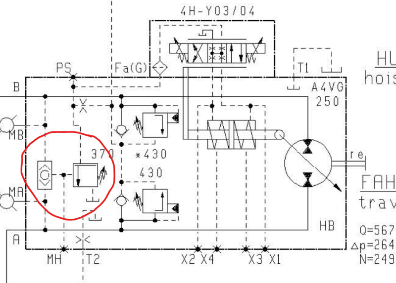
I got a Hydraulic Winch which runs out of two pumps which are paralleled, the winch is rotated by 4 A6VM motors, the whole system is a closed loop system. i got currently a problem where i am losing charge pressure from the compensation pump during winch operation, i suspect one of the motors are leaking inside and causing this issue because we had all pumps replaced not long ago on the system. My problem is that i'm unable to find any data for the flow rate on the Case Drain on these motors (A6VM), any ideas from some one who have experience with these motors on what the case drain flow should look like ?.


Thanks

Marvin
 
Replies continue below

Recommended for you

Hello,

The motor with the coldest crankcase is the one with the most internal leakage.

If you gave more information, you would have specific answers.

Where is the exchange valve (s)?

With an infrared thermometer and by thinking a little you can make a diagnosis.

cordially
 
The system does not have any valve. The rotation of the winch is controlled by the pump swash plate angle.

I have checked all the motors and the case drain on all of them looks normal.

I'm currently having a strange problem with one of the pumps (A4VG 250), where one will produce pressure and the other will not even bother moving the gauge pointer at all, i am trying to actuate it manually in both directions but it looks like the swash plate is not adjusting. The boost pressure is all fine.
 
Hi 73lafuite. I was going to send the diagram of the system i am working on once i reached back home, now that i am back, you can view the diagram in the attachment. any help or ideas would be very appreciated.

The diagram shows the full main system, the current problem is just with the winch. everything else is working OK. for any details just let me know.
 
 https://files.engineering.com/getfile.aspx?folder=69de6065-20e4-46a9-90fb-3afab40ee538&file=D.jpg
Hello,
It's really complicated your system.
Are you losing the charge pressure at the TAP60 pump?
The displacement of A6VM engines depends on the pressure at the X port. Look at the reference on the nameplate and take the instructions to know what pressure it takes at the X port to increase the displacement. Have you checked the pressure on the pilot X?
Each engine is swept through the U port, so the crankcases should not get too hot.
I can't quite understand the Liebherr scheme. How can fresh and filtered oil be injected into the closed circuit of the winches in exchange for hot and polluted oil ????
I don't think I'll be able to help you from a distance. I am not qualified enough.
 
image_aa75kw.png


Here's your hot oil valve (and the answer to 73lafuite's question about where the hot oil goes). A worn hot-oil relief is quite a good way of losing charge pressure.

But then I'm not 100% convinced I'm looking at the same motor as you are - the component labelling on the drawing is a bit strange.

A.
 
If you start it up from cold and lift a heavy load the motor that has a leakage will heat up the leakage line before the others. If you have access to a good FLIR camera that can be helpful (although shiny metal gives unreliable results). Using your hands or a cheap IR-gun might also work.


73lafuite "How can fresh and filtered oil be injected into the closed circuit of the winches in exchange for hot and polluted oil ????"
The normal leakage will exchange the oil. I would not design it like that, I would use a flushing valve but systems without flushingvalves do exist.
 
Tried the Flir camera on the motors but couldn't find any thing, i even tried to measure the drain using a bucket but that didn't reveal any thing wrong with them. Strange thing now is that one of the A4VG pump is not producing any pressure, i am trying to accuate it by hand uaing a screwdriver to push the solenoids on top, it doesn't respond at all,,, the other pump work ok. Could it be a faulty servo valve ?.

I lack detailed documentation on these pumps, all i can find online is general pump specs.
 
Hello,
1) My remarks which do not help barbican: Totally agree with Jacc, the valve serves well to cancel the flow of the pump when the pressure is too high. Indeed I have already seen closed circuits without exchange valve (example lawn mower). But it is not serious. Any particles that are a little large will be laminated in the distribution glasses, the piston pads and will break up into millions of particles the size of several molecules to manage to come out with the internal leaks. And so as long as it's in the closed loop it scratches and tears off other particles. Liebherr should have put a nozzle and a normally closed 2/2 directional valve between the A of the engines and the tank. And supply the distributor when the load increases.
2) For barbican:
2a) It is normal not to detect anything with the Flir camera, because you have a sweep of cold oil which comes through the U port of each motor.
2b) Can you answer my 2 questions of June 22, 6:42 am?
2c) Does the winch operate without load? In 2 ways? Do you lose the boost pressure at the TAP60 pump when there is a large load? Or if you leave the winch brakes closed? Does the A4VG180 pump on the same shaft as the faulty pump 250 give flow? If not, then the coupling is not in place.
 
Hi 73lafuite.

The winch will operate without load but only in one direction which is UP, the down direction will cause the pumps to lose charge pressure,

When there is a load on the winch, the problem will be apperent mostly when lowering the load, the charge pressure will drop at that time just under 10 bars. It should be sitting at 35 bars.

The coupling is fine because the A4VG 180 pump on the back of the A4VG 250 pump is operating fine. I
 
Indeed, it looks like a big internal leak like the separation of distribution plate. I would still check if a RHZ 20 SR charge valve is not stuck open.
 
Which port on the hoist gear pump is driven by TAP60?

- I think I found it. It appears to control flow to shift the swash plate, so it's not charging anything.
 
It looks like TAP60 also is to release the brakes; if it's not producing sufficient pressure nothing will move.

Did the system ever function right after all the pumps were replaced? Perhaps moving the valve block from one hoist pump to the other would tell if there is a failure in the valve block or the pump.
 
Status
Not open for further replies.
Back
Top