Eng-Tips is the largest engineering community on the Internet

Intelligent Work Forums for Engineering Professionals

  • Congratulations waross on being selected by the Tek-Tips community for having the most helpful posts in the forums last week. Way to Go!

Pumping downhill 3

Status
Not open for further replies.

swazimatt

Civil/Environmental
Aug 19, 2009
233
0
0
NZ
I am looking at a project that involves a wastewater pump station. The initial design pumped to the crest of a hill and then gravity flow to another WWPS. this existing WWPS pumps a short distance uphill and discharges into the gravity network. The existing WWPS is much smaller than the one we are designing so will ultimately require a complete upgrade which is one of the reasons i am looking into pumping the full length to the same discharge manhole (bypassing the second pumpstation)
Another reason is that once we have dropped down the main hill there is a second small hill so the gravity network ends up being fairly deep so by pumping we can go with minimum cover.

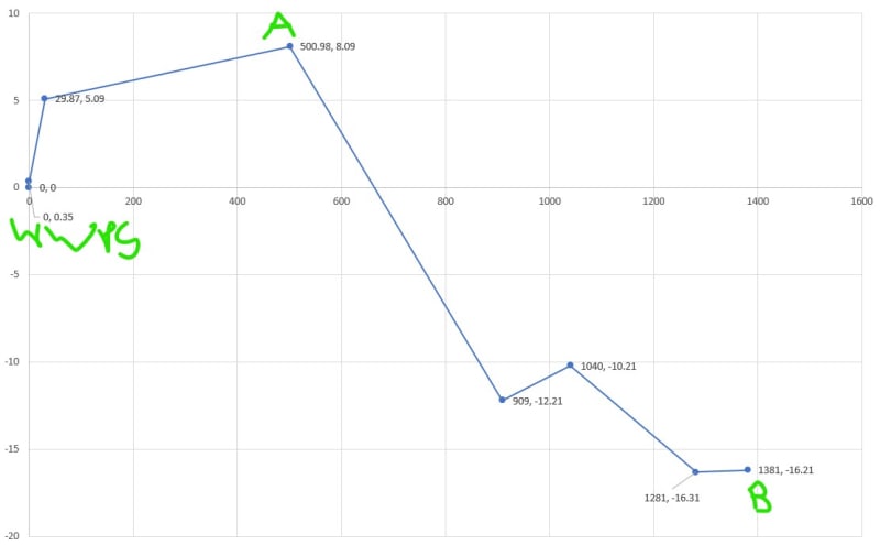
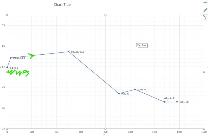
The crest is at chainage 500 with a static head of 7.8m and the full system (pipe length) is 1381m with a static head of -16.6m
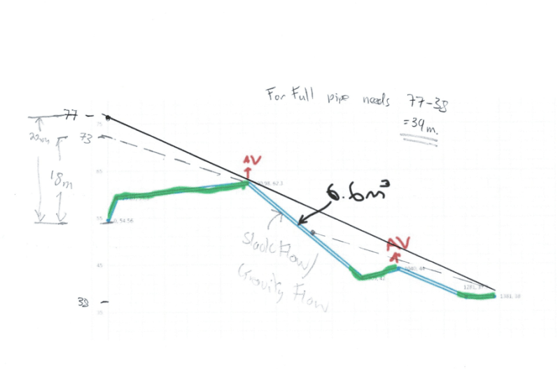
For the pipe size i have selected (v=1.4m/s) the total dynamic head is 22.5m and 24.02m

I know that the selected pump needs to initially lift over the high point and still operate when the full pipe is charged.
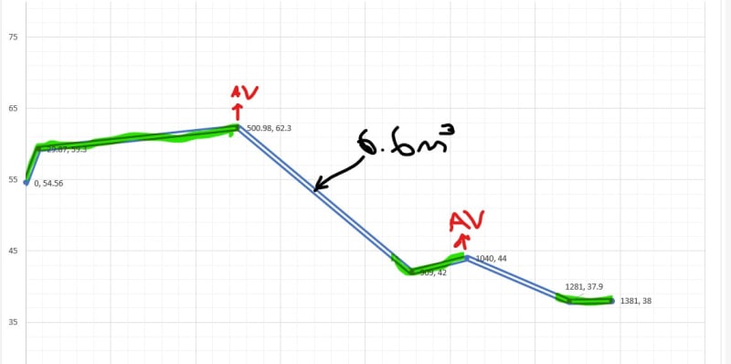
We will have air valves and scour valves at the high and low points so we will not be creating a siphon when the pump switches off


What are the requirements to know if once the first duty point is met the pump will be able to fill the downhill portion of the pipe and create a charged pipe?

Having researched it i believe that if the system curve for the initial high point meets the pump curve at a higher flow rate than the full system curve / pump curve intersection then the pipe will eventually fill, and then the pipe friction will force the duty point to move from the crest to the full (does that sound right?)

 
Replies continue below

Recommended for you

If you have an air release / vacuum breaker valve at the first high point, and if the second hill is lower than the first, then the flow from the first high point all the way to the final discharge point should be by gravity alone and have no impact on the pump head required.

But I must confess to being a bit confused by your description. A sketch would help us understand what you are trying to accomplish.

Katmar Software - AioFlo Pipe Hydraulics

"An undefined problem has an infinite number of solutions"
 
This would be much better to present this on a profile drawing so we can see the relative positions of the high and low points and tie ins to the gravity sewer.

It looks like you have more pressure drop than static loss so this should flow as a full pipe and at 1.4m/sec you will flush out any air in the system.

But a decent drawing in section view with pressure / head and static height differences would help a LOT.

Remember - More details = better answers
Also: If you get a response it's polite to respond to it.
 
Hard to speculate on pressure drop without knowing pipe diameter.
Velocity is not very high, yet the pump head of 24m is nearly equal to the 7.8m -(-16.6 m) heads.
Do you need 48m head, 24m pump head + 24.4m gravitational head, to move your flow at 1,4m/s?
I may be confused, but something does not sound right here.

Id rather see chainage and elevations on that sketch, rather than static height differences.
 
At 1400m of pipe I'm not getting too worried.

But yes, it seems a bit too close for comfort.

We await the profile drawing.

Remember - More details = better answers
Also: If you get a response it's polite to respond to it.
 
thanks for the replies
have attached 2 simplified long sections (Chainages and static head, and chainages and elevation)
Pipe diameter is 146mm ID PE pipe
Duty point for the pump is 27.86 l/s at 26.1m for the first crest (A) and 25.8 l/s at 26.6m for full length (B)

long_section_static_head_zpfana.jpg

long_section_yi1fso.jpg
 
I suppose the next thing i will need to check is if i will have enough volume to pump to fill the pipe - it is a wastewater pump station so dependent on flow into the wetwell and the full length will be 23m3
the downhill portion will be 6.7m3 which may just fill under peak flow conditions but the rest of the time this be working like a reverse siphon especially if i have air valves.

I don't think this will work for a WWPS BUT THE ORIGINAL QUESTION STILL STANDS - HOW WOULD I KNOW IF THE PUMP FILLS THE DOWNHILL SECTION (assuming it is pumping from an unlimited source)

pipe_full_2_ux0zfe.jpg
 
If the pipe length between points A and B is 1000 m and the difference in height is 24.3 m then the flow rate with the pipe full of water would be around 36.5 l/s (velocity = 2.2 m/s). Note that this assumes a vacuum breaker at point A, making the pressure in the line at Point A atmospheric.

If your flow rate is less than 36.5 l/s then the pipe will not run full. At 28 l/s only the last 120 m of the pipe down to the 909, 42 point will run full.

Katmar Software - AioFlo Pipe Hydraulics

"An undefined problem has an infinite number of solutions"
 
This is why you draw profiles.

The answer is simple.

From your end point, draw a line back from your arrival head ( presumably near zero if you're emptying into a gravity manhole or something) at the hydraulic slope ( m/100m) you've calculated for the flowrate and pipe size.

If it hits the elevation of the ground before getting over the high point, then you're in slack flow or gravity flow mode and the pipe d/s the high point will never fill unless you increase the back pressure either at the end or by flowing faster. Having a fixed back pressure at the arrival point isn't rare, but more difficult for waste water as things like control valves tend to plug up. You would need about a 10m back pressure at your arrival point to flow in a full pipe at the size and flowrsate you're working to.

To fill the line you would need to follow the black line and hence have an overall head loss of 39m, compared to your 26m. Your current overall head loss of 26m ( which sounds about right) is the dashed lone and you can see that this has a break in it where you will get slack flow / gravity flow

Your calculation about the pump head doesn't look correct as you haven't allowed for the high point correctly. If you track back on the dashed line from the top of the first hill you will see you only need 18m head at your flow rate. Oh and your flowrates can't be different for a steady state model. Mass in = mass out.

Katmar - he's shown on the drawing it's 1381m long from A to B. I'd be interested to know what the analysis says.

For waste water flowing in gravity mode isn't a big issue compared to other types of pipelines and what you really need to do is look at flows and volumes, then worry about things like this later.

image_tw1ulv.png


Remember - More details = better answers
Also: If you get a response it's polite to respond to it.
 
LittleInch (Petroleum) said:
Katmar - he's shown on the drawing it's 1381m long from A to B. I'd be interested to know what the analysis says.

See the first sketch. Point A is at 500.98 and Point B at 1381.00. Difference is 880.02. I used 1000 just to be a bit conservative. Maybe I should have just used the 880. The conclusion, as you have shown with your much more thorough analysis, remains the same.

Katmar Software - AioFlo Pipe Hydraulics

"An undefined problem has an infinite number of solutions"
 
LI Thanks for saving me the time of doing that sketch! *

And why must this flow full? Gravity flow wastewater lines do not need to flow full.

Digging a bit deeper at point B and eliminating the 2m rise for a flatter slope would make sedimentation at that point much less likely. (Gravity flow wastewater pipelines should generally be comprised of straight pipes connecting at manholes.) Otherwise a manhole access point could be convenient there. Speaking of which, you could probably have a couple of them anyway.


Katmar,

My deep apologies - I thought you wouldn't have got it wrong.

I normally like full pipes all the time, but them I'm not a sewer design person....

Remember - More details = better answers
Also: If you get a response it's polite to respond to it.
 
It is kind of strange, however a pipe under gravity flow conditions will have the highest flow rate when 60% full and often have flow rates well under that. It is the level where Q to f ratio is highest, as filling the top region adds proportionally much more friction for each rapidly decreasing area of flow.

Especially those lines devoted to carrying storm water. Riyadh, Jeddah, Al Khobar have mosquitoes primarily for that very reason. Most of the time, no flow with some stagnant pooling and nice cool sewers makes for a good breeding ground.

 
Although 94% gives the maximum flow, the maximum velocity occurs at about 81%. This can be important in waste water piping where solids need to be kept in suspension and transported with the liquid. This means that gravity pipes are seldom run full and 60% is probably the point where most such lines run. When a surge occurs you can't just ask nature to wind up the gravity constant for an hour or two.

Katmar Software - AioFlo Pipe Hydraulics

"An undefined problem has an infinite number of solutions"
 
A target flowrate at 60% depth would make perfect sense. It was from a 1973 lecture and actually I remember more about a possible trip to Vietnam than I do about wastewater flow, A dusty pearl. Thanks for the "screen refresh".

Yes, I haven't thought about it like that. There's a reason that g comes with a little [sub]c[/sub] attached. No VFD's there.

I also remember "no backslopes" too, so I hope they dig that 2m bump out of the profile.


Eng. swazimatt ,

Will you post the system curve vs pump characteristic curve for the both cases ; pumping to pt (A) and pumping to pt (B) full length...

katmar (Chemica) has a valid point... if the full pipe flow with gravity 36.5 l/s from pt A to B , in this case, your second case ( 25.8 l/s at 26.6m for full length ) could not be valid...
 
Hturk,

I suspect that's because he's not allowed for the hill and just calculated pressure drop along the entire line assuming it is flat.

Remember - More details = better answers
Also: If you get a response it's polite to respond to it.
 
Status
Not open for further replies.
Back
Top