Eng-Tips is the largest engineering community on the Internet

Intelligent Work Forums for Engineering Professionals

  • Congratulations waross on being selected by the Tek-Tips community for having the most helpful posts in the forums last week. Way to Go!

Pumping downhill 3

Status
Not open for further replies.

swazimatt

Civil/Environmental
Aug 19, 2009
233
0
0
NZ
I am looking at a project that involves a wastewater pump station. The initial design pumped to the crest of a hill and then gravity flow to another WWPS. this existing WWPS pumps a short distance uphill and discharges into the gravity network. The existing WWPS is much smaller than the one we are designing so will ultimately require a complete upgrade which is one of the reasons i am looking into pumping the full length to the same discharge manhole (bypassing the second pumpstation)
Another reason is that once we have dropped down the main hill there is a second small hill so the gravity network ends up being fairly deep so by pumping we can go with minimum cover.

The crest is at chainage 500 with a static head of 7.8m and the full system (pipe length) is 1381m with a static head of -16.6m
For the pipe size i have selected (v=1.4m/s) the total dynamic head is 22.5m and 24.02m

I know that the selected pump needs to initially lift over the high point and still operate when the full pipe is charged.
We will have air valves and scour valves at the high and low points so we will not be creating a siphon when the pump switches off


What are the requirements to know if once the first duty point is met the pump will be able to fill the downhill portion of the pipe and create a charged pipe?

Having researched it i believe that if the system curve for the initial high point meets the pump curve at a higher flow rate than the full system curve / pump curve intersection then the pipe will eventually fill, and then the pipe friction will force the duty point to move from the crest to the full (does that sound right?)

 
Replies continue below

Recommended for you

@LittleInch

I am not sure if i follow you here. Your black line shows a difference of 22m above the pump, so if i am using a pump head of 25m then the line will be about 2m above point A. My understanding of a pump is that is adds energy to a system. If you have an overall drop (ie negative static head) this will "assist" the system so will not need the full 39m static head you have mentioned?

@Katmar
Is this how you can tell if the pump will fill the portion of pipe or does this only apply to when the pump stops and the air valve opens?
While the pump is operating the Air valve will be closed as the HGL will be above the Air valve so surely with time the friction in the pipe will slow down the flow and allow the pipe to fill all the way back to A and then flow under full conditions controlled by the pump?

It makes sense that the the portion from A to B will operate under gravity conditions (siphon flow?), so for the pipe to fill the pump would need to pump at a higher rate than the gravity flow


@1503-44

The main reason for investigating this is that there is a small WWPS at 1281,37.9. This WWPS and it's rising main will need to be upgraded to cater for the new development (if we pump and gravity flow to it), if we ccan bypass it and pump all the way to the discharge manhole we won't need to upgrade it and won't have deep pipes either.

If we allow the pipe to flow partially full on the long downhill there is a good chance that solids will settle in the low points and i will need to demonstrate that intermittent flow will be able to resuspend solids from the low points (inverted siphons). A full pipe from start to end will be controlled by the pump (?)
 
@katmar
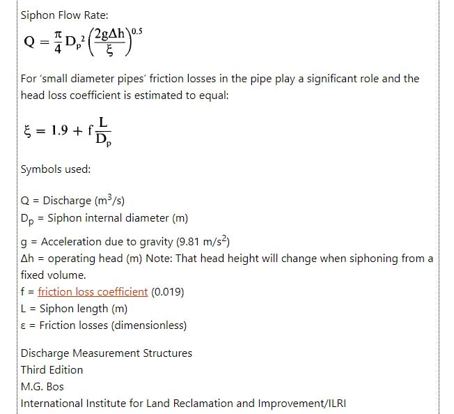
If i use the siphon flow formula from the WWPS (54.56) i get a flow rate of 22.4 l/s, using this formula:
siphon_formula_urnn2y.jpg


so surely we shouldn't be calculating the flow rates from point A?
 
swazi,

you can't talk head without flow.

What my line shows is that if you want to maintain a full pipe system you need to have to create, over the length of the pipe, a head of 39m. This is complicated a little by the fact your start point is 16.6m higher than the end point so the requirement is then 23m when measured from ground level at the entry point.

Katmar has estimated 36l/min is needed, but used a slightly longer pipe .

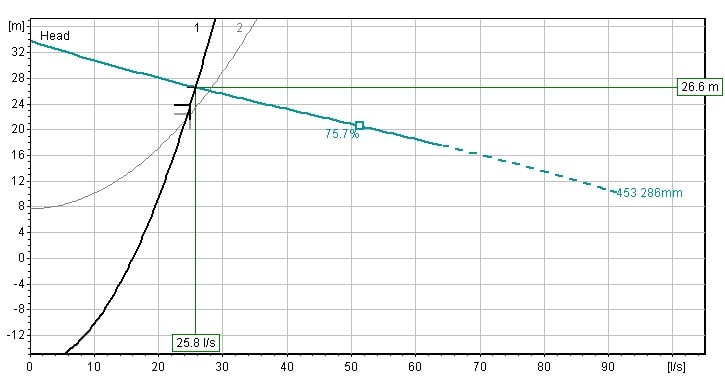
I used your figures in the various posts above and might have got these wrong, but the basic principle applies. Looking at your system curves, I may have misinterpreted the earlier figures as I didn't have the system curves to view and yes, it seem that if these are correct, to generate the required head loss per metre to create a full pipe, you need to be doing more than 23-24 l/sec, which if you're flowing at closer to 26 l/sec, you have enough flow, head and pressure drop to create a full pipe flow.

You don't have much margin here though and a few metres here or there makes a lot of difference.

But in any event, why would solids settle on the down hill section when you're flowing at 1.4m/sec?

What that system curve is telling you is that up to ~24l/sec, you pumping head is driven by the initial static head plus friction losses in the section from the pump to point A
To the left of that intersection point between 1 and 2 you can effectively see that the top of the liquid column in the pipe going to point B gradually rises ( just extrapolate line from point B back to start point using your curve. - so e.g. at 20l/sec the top of the liquid column going downhill would be at about elevation 57 or 58m)
At the intersection point of the two curves, you now have (just) full pipe flow along the entire system.

At this point the friction effect of moving fluid along the whole length of the pipe takes over so your curve 2 beyond the intersection point is no longer valid and should be deleted.
Now you're running a full pipe, look at curve 1 only.
So the intersection point with the pump curve gives you your 26.6m @ 25.8l/sec

Even if part of the downhill section ran empty, there would still be quite a large head difference from the top of the liquid column on the downhill section to your end point which generates quite a high velocity, more than enough to sweep out anything which has settled in the bottom of the pipe during no / low flow situations.

It would have helped a LOT if you'd posted the system curves with the other data...

Remember - More details = better answers
Also: If you get a response it's polite to respond to it.
 
Sure, the pump adds energy to the system, but it needs to add enough to pump your flow rate up the hill PLUS overcome frictional head of the remaining pipe. Downhill is not a free ride at any flow rate you want. If your pump only provides enough energy to only get to the top of the hill, the remaining pipe's friction will determine your flow rate. Flow in the downhill slope will not be more than what the difference in energy gained going down - flowing friction will allow. Your siphon flow rate equation must include friction of the 1381m length. Whether the pipe flows full or not depends on that flow rate sustaining full flow down the given slope.

 
We are getting ourselves into the weeds here. Forgive me if I go back to first principles.

The first thing to agree on is that we are designing for steady state. If it is not steady state then you should be designing for the worst case situation. Otherwise all bets are off the table.

Although the grade line diagram as shown by LittleInch is a great way to summarize and present the final design, I do not like actually doing the design that way because I am not good at drawing and I do not have software that will draw the grade line for me. I prefer an algebraic/analytical approach.

I would also not term any part of this design a siphon. It is a standard gravity flow problem.

OK, so if we are talking of steady state it means that if you take a cross section at any point along the line the flow rate will be the same. During start-up and shut-down this will not be true, and we might need to check whether that is relevant here for pump sizing etc.

SwaziMatt_djb7l7.png


If we are doing an analytical design we have to start at a point where we know both the flow rate and the pressure. We know the flow rate at every point (steady state) so that is not a problem. We do not know the pressure at the pump discharge because we have not solved the pump vs system curve balance - so that is not a good point to start. The obvious point to start from is the final discharge (Point B). We could possibly start from points A or E because the pressures there are fixed at atmospheric if breather valves are installed but we will keep those as fallback options.

I will assume that the flow rate is 28 l/s, but you can make it whatever suits your situation. The distance from F to B is 100 m and the change in elevation is +0.1 m. The friction loss is 15 kPa and the static loss 1 kPa so if Point B is atmospheric (call it 101 kPa abs) then the pressure at point F is 117 kPa abs and we now have another fully defined point (i.e. we we know the flow rate and the pressure).

Now we can take the next step and analyze section EF. The length is 241 m and the change in elevation is -6.1 m. The friction loss (if the line is full) would be 35.5 kPa and the static pressure is a gain of 60 kPa (again, if the line is full). This means that the pressure at point E would be 117 + 35.5 - 60 = 92.5 kPa abs (-8.5 kPa gauge). We do not want negative gauge pressures anywhere in a gravity line and we need to install a breather valve at E to ensure that the pressure there stays atmospheric (1503-44 will surely disagree).

Installing the breather valve at E means that the upper part of section EF will not run full. If it were full the pressure available would be more than is required to achieve the 28 l/s flow and there would be excess flow for a while until steady state was re-established. At steady state the line from E to some point G will run part full and from G to B it will run flooded.

The analysis for sections DE and AD will be the same as the above, and lead to the conclusion that the pressure at point A must be held at atmospheric with a breather valve and the line from A will run part full down to some point C.

The line from the WWPS to point A is 501 m long with an elevation change of +8.09 m. At steady state (28 l/s) the friction loss will be 74 kPa and the static head 80 kPa. The pump will therefore have to deliver 154 kPa or about 16 m of head. At start-up the head will be less and to avoid over loading the pump motor the pump should be run with a partially closed delivery valve to ensure that the pump "sees" 16 m until the line to A is full.

Why is my calculated pump head less than yours and also less than LittleInch's? The reason is that I have allowed for some of the line to run part full where there will be no static head loss or gain. If you install a pump with a head of 25 m the net head change between the WWPS and Point B will be 41 m and the line will run full all the way with a flow rate of about 40 l/s (edited from 50 l/s) and there will be no breather valves required (but I would still put them in, just to be safe).

I disagree with 1503--44's latest post. The pump does need to pump up to point A only. My earlier analysis showed that there was sufficient driving force from gravity alone to achieve a flow rate of 36 l/s from point A to Point B. If you need a flow rate less than 36 l/s then all the pump needs to do is to get the liquid up to point A. Nature will do the rest for you.

Katmar Software - AioFlo Pipe Hydraulics

"An undefined problem has an infinite number of solutions"
 
Katmar,

Looks to me like your friction losses are lower than those calculated by swazi.

No idea who is more accurate, but suspect you are.

Like I said above, this system is right on the edge between full and gravity flow using swazis figures and a long way at ~26 l/sec using Katmars figures.

Remember - More details = better answers
Also: If you get a response it's polite to respond to it.
 
Hey LittleInch - I did mess up the overall friction loss. See edit above. I have corrected my flow rate from 50 l/s down to 40 l/s. This is a bit more than my previous 36 l/s because as you noted I had assumed the pipe to be longer than actual.

Katmar Software - AioFlo Pipe Hydraulics

"An undefined problem has an infinite number of solutions"
 
Katmar, I didn't run any numbers to see if gravity was enough to overcame friction on the downslope or not, so going to the top of the hill may indeed be enough to do the job. I'll let you and LI hash that out. Have fun.

 
There's something strange going on here that's maybe me, but when I try to get head loss figures for the following info I'm getting numbers around 20m head loss total or 1.4m/100m for friction losses for ~25 l/sec which seems to equate well with Katmars.

swazi, For the same flow (25 l/sec) you seem to be getting about 3.2 m/100m

PE pipe
Pipe ID 146mm
Length 1380m
Flow 25 l/sec

How are you calculating this?

Remember - More details = better answers
Also: If you get a response it's polite to respond to it.
 
How did you do it? It might be faster if everyone agrees on your method, rather than asking for another calculation, which might be just some GIGO from some unknown spreadsheet. What do you think?

 
Three or four online sites offering calculations and graphs etc.

All came back with results approaching katmars.

Using ID makes a big difference, but the flow rate and velocities add up.

So not sure.

Remember - More details = better answers
Also: If you get a response it's polite to respond to it.
 

Eng. swazimatt ,

I could not look to the previous posts in detail but looked to the pump characteristic curve and system curve for both cases ;

Let me explain my thoughts;


-With this pump characteristic curve and system curves , the pump just rises the the liquid to point A with a discharge 27.8 lt / sec.

- the conveyance capacity of pl from pt (A) to pt (B) with gravity flow (having available head 24.30 m and length L=880 m is , 38 lt / sec.. so, the flow will be 27.8 lt / sec. and full pipe flow from pump to pt A.


- The required head to convey 27.8 lt/ sec from pt A to pt B is , around 13.8 m.

- Open channel flow will develop below pt A to dissipate the energy.


If the discharge around 25 lt/ sec. is OK, i will suggest you to install valve at pt B in order to provide full pipe flow ..

Good luck..


I am using standard Darcy-Weisbach, but with a roughness of 0.005 mm (0.0002 inch) for the PE pipe. This gives me a friction factor of 0.0157, a velocity of 1.49 m/s and a pressure drop of 1.22 m/100 m at 25 l/s. At 28 l/s these change to 0.0154, 1.67 m/s and 1.50 m/100 m.

Katmar Software - AioFlo Pipe Hydraulics

"An undefined problem has an infinite number of solutions"
 
I need to read through all of this pretty slowly to get my head around it all ... there will be more follow up questions!

The most likely reason for the friction loss differences is that the council requires we use Colebrook White with a k value of 1.5 (of when it becomes very old wastewater line I think!)
 
swazimatt (Civil/Environmental)(OP) said:
We will have air valves and scour valves at the high and low points so we will not be creating a siphon when the pump switches off

Air valves and scour valves are not recommended on sewage force mains as the pumped contents will cause the valves to clog and fail. Then you will have to clean up the spilled mess.

The preferred solution is to pump continuously, keep the velocity above 3- 4 ft/sec, and to use a back pressure valve on the end of the force main to keep the force main from draining.

Refer to Pumping Station Design by Garr Jones.

With all due respect to the previous posters, they share a common trait, they have little to no experience with pumping sewage. If you want help, refer to Garr Jones' comprehensive book to avoid making a mistake:

Pumping Station Design
 
bimr (Civil/Environmental) said:
With all due respect to the previous posters, they share a common trait, they have little to no experience with pumping sewage. If you want help, refer to Garr Jones' comprehensive book to avoid making a mistake:

I have read the section "Recommended Options for Wastewater Systems" on page 7.2 in the 3rd Ed of Garr Jones' book. In this section he goes into quite some detail regarding what type of breather valves to use, how to install them and how frequently they should be serviced. But I find no mention of back pressure control to avoid slack flow. In fact, the index does not even mention slack flow. Can you please point us to the relevant section in the book where we can read about back pressure valves.

As in all engineering design, the final decision comes down to economics. Is it cheaper to incur the additional power to provide the higher pressure when installing back pressure valves, or to set up a maintenance program to service the breather valves, or to accept that there will be a spillage once a decade or so.

Katmar Software - AioFlo Pipe Hydraulics

"An undefined problem has an infinite number of solutions"
 
If there is one thing I've picked up from various discussions on here, it is that "waste water / sewage" has many meanings, but one item which sticks out is to avoid anything which can result in a constriction or other internal device which can clog up, or get string, weeds, paper etc wrapped around it.

Hence in the past when control valves have been suggested for such systems, there is usually the response that they don't work well for waste water systems and I can see why.

The ongoing issue here which the OP hasn't come back to us yet is that we seem to be a long way apart on the pressure drop for the same flow rate in the same pipe.

Remember - More details = better answers
Also: If you get a response it's polite to respond to it.
 
I could never determine if its a force main or a gravity flow line, or if the OP wants both.
A force main might need a control valve, a gravity flow line, not so good. Gravity flow waste pipe that long supposedly needs some clean out manholes. It should have well controlled velocity by maintaining proper slope and avoid reverse slopes. Since none of those firmed up, as well as little else, force mains not flowing full dont really have a pressure drop. Siphons, gravity flow. Valves, vacuums. Anyway, looked like too much for me, so I just thought I would just try to stay out of it and see what color of elephant results. Not meaning to say that things are going badly, just that it looks like getting there will be a long arduous process.

 
Status
Not open for further replies.
Back
Top