Continue to Site

Eng-Tips is the largest engineering community on the Internet

Intelligent Work Forums for Engineering Professionals

  • Congratulations SDETERS on being selected by the Eng-Tips community for having the most helpful posts in the forums last week. Way to Go!

Pumping downhill 3

Status
Not open for further replies.

swazimatt

Civil/Environmental
Aug 19, 2009
275
I am looking at a project that involves a wastewater pump station. The initial design pumped to the crest of a hill and then gravity flow to another WWPS. this existing WWPS pumps a short distance uphill and discharges into the gravity network. The existing WWPS is much smaller than the one we are designing so will ultimately require a complete upgrade which is one of the reasons i am looking into pumping the full length to the same discharge manhole (bypassing the second pumpstation)
Another reason is that once we have dropped down the main hill there is a second small hill so the gravity network ends up being fairly deep so by pumping we can go with minimum cover.

The crest is at chainage 500 with a static head of 7.8m and the full system (pipe length) is 1381m with a static head of -16.6m
For the pipe size i have selected (v=1.4m/s) the total dynamic head is 22.5m and 24.02m

I know that the selected pump needs to initially lift over the high point and still operate when the full pipe is charged.
We will have air valves and scour valves at the high and low points so we will not be creating a siphon when the pump switches off


What are the requirements to know if once the first duty point is met the pump will be able to fill the downhill portion of the pipe and create a charged pipe?

Having researched it i believe that if the system curve for the initial high point meets the pump curve at a higher flow rate than the full system curve / pump curve intersection then the pipe will eventually fill, and then the pipe friction will force the duty point to move from the crest to the full (does that sound right?)

 
Replies continue below

Recommended for you

swazimatt said:
...friction loss differences is that the council requires we use Colebrook White with a k value of 1.5 (of when it becomes very old wastewater line I think!)

I missed that earlier.

Indeed this looks like a roughness of 1.5mm?

Try a roughness factor of 0.005 in the same units and see what you get.

Designing a PE line using friction factors based on corroded cast Iron is just plain stupid and will give you the wrong answers. They probably justify it by saying it is conservative and will give you a bigger pipe, but that doesn't help you in your situation when it would mean you're then operating on gravity flow instead of full pipe pumped flow and also means your pump is oversized.

Remember - More details = better answers
Also: If you get a response it's polite to respond to it.
 
Good comments from LittleInch. In addition to the change in the roughness whoever has specced the flow rate has hopefully included some growth. So we need a design that works now with smooth pipe and low flow, but will also work in 10 years time with rough pipe and a higher flow rate. You don't read this stuff in the fluids texts.

Katmar Software - AioFlo Pipe Hydraulics

"An undefined problem has an infinite number of solutions"
 
"Make every effort to eliminate (or, at least, to mitigate) transients by avoiding knees, high spots, steep gradients near the pump, and air (or, much worse, vacuum) in pipes. When any of these conditions cannot be avoided, use a combination of pipe strength and control strategies to provide adequate protection at reasonable cost."

"Use every practical means to avoid the necessity for such valves in wastewater service because of problems with grease and excessive maintenance. Try to design the force main with a positive gradient to its discharge. If that is impossible, design for an air-scouring velocity to occur at least once per day."

"Some engineers object to the use of conventional air-vac valves for wastewater under any circumstances and have always managed to find a different control strategy, but see Section 7-1 for one alternative."

"The reasons for using V/S pumping for wastewater include the following: • Continuous pumping and the very short liquid residence time in V/S operation reduces (1) the deposition of organic solids—a problem in C/S pumping because of the difficulty of re-suspension; (2) putrefaction—so the wastewater is easier and less costly to treat; (3) the production of odors and corrosive, poisonous gases; and (4) cyclic rise and fall of the water surface with the resulting pumping of sewer gases into the atmosphere."

"Optimize the size of the pipe based on the life-cycle cost, including power and capital costs. A practical maximum velocity is about 2.4 m/s (8 ft/s). Higher flow results in greater headlosses and may result in excessive water hammer. The lowest design velocity that should be used for raw waste water is 0.6 m/s (2 ft/s) to keep grit moving, and a peak daily velocity of 1.1 m/s (3.5 ft/s) is desirable to resuspend settled solids. A lower minimum velocity of 0.5 m/s (1.6 ft/s) can be tolerated if a twice-daily velocity of 1.1 m/s (3.5 ft/s) is attained."

"Use the correct friction coefficients for pipes. Excessively rough friction factors, although conservative with respect to the carrying capacity of the pipe, are dangerous for the selection of motors and pumps. When determining the carrying capacity, a conservative practice is to use C = 120 for lined or plastic pipe (or C = 100 for unlined pipe), which conforms to Ten-State Standards; then redraw the system curve for C = 145. Make sure that the system can operate at both conditions or at any intermediate condition."

 
1503-44 said:
I could never determine if its a force main or a gravity flow line, or if the OP wants both.

The original question was for it to be a force main so that we avoid having to upgrade the smaller pump station at F.

In my earlier post i realised that it will not be able to work as a conventional force main as it is wastewater so will be pumping intermittently and the volume in the wetwell will not be enough to re-fill the downhill section A-D so there will be "slugs" of flow at 25l/s every so often (depending on flow from the developments gravity network) and i am not sure how i would demonstrate that this "slug" would be enough to resuspend solids sitting in the low points and carry them over the humps

IT is now an academic question from my side to understand how i would know what flow rate is required to create steady state flow through the entire pipe (assuming the pump had sufficient wastewater to pump continuously)


BIMR said:
Air valves and scour valves are not recommended on sewage force mains as the pumped contents will cause the valves to clog and fail. Then you will have to clean up the spilled mess.

The preferred solution is to pump continuously, keep the velocity above 3- 4 ft/sec, and to use a back pressure valve on the end of the force main to keep the force main from draining.

Refer to Pumping Station Design by Garr Jones.

It would be great if you had a link for this book as a PDF ;-)

I know sewage mains are best without air valves, but there is no real choice in this situation. (amd manufacturers are pretty adamant that they don't clog up anymore)
This has raised another problem though, and that is of noise pollution. There is a good risk of whistling happening when the long downhill drains every time the pump turn off and air is sucked into the pipe - not ideal in a residential area (especially in small town NZ where you can hear a pin drop any time after 6pm)
 
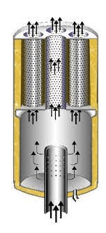
To avoid the whistling you need a silencer. Best ones are probably just an reducer and a bit of pipe up a couple of sizes from your vent and stuffed with iron wool and a few holes in the side of the bigger pipe.

Or just buy one e.g.
Search "vent silencer drain pipe"
image_piaoxr.png

Remember - More details = better answers
Also: If you get a response it's polite to respond to it.
 
Status
Not open for further replies.

Part and Inventory Search

Sponsor