Continue to Site

Eng-Tips is the largest engineering community on the Internet

Intelligent Work Forums for Engineering Professionals

  • Congratulations GregLocock on being selected by the Eng-Tips community for having the most helpful posts in the forums last week. Way to Go!

Pumping over a high point 2

Status
Not open for further replies.

ccc89

Civil/Environmental
Jun 17, 2021
2
I'm currently working on a pump station design and had a question about the static head and total head of the system. I will be pumping out of a wet well, over a high point in the discharge line as it crosses over a levee, and into a river. The max water surface elevation in my wet well is +5' for my design storm, the levee crown is at +31', and the river stage is a +12.5'. I will have 3 pumps set in parallel with a single discharge line and their floats will be set at different on/off elevations. My wet well will always hold water due to submergence requirements on the submersible pumps down to a -8.5' elevation. An air release/vacuum valve will be installed at the high point in the discharge line and the discharge line will be submerged.

Is my static head the difference in the water surface elevations in my wet well when all pumps are off and the river (12.5'--8.5' = 21')? Or is the static head the difference in the wet well to the high point (31'--8.5' = 39.5')?

Also, to calculate the friction losses in the system should I use the flow rate when all 3 pumps are running or only 1 pump running?
 
Replies continue below

Recommended for you

39.5 ft
When using a vacuum breaker, that also breaks siphon action, so you cannot take any benefit from having a siphon to reduce overall head required to 21ft.

If you will run up to 3 pumps, then use the 3 pump flow rate.

You might want to think about a couple of very important options when designing this system. Not using a vacuum breaker valves and selecting at least one VSD controlled pump. That way you could always easily keep the siphons primed by using full RPM head of around 40ft from your VSD pump to start up the siphon action.

After the siphon action was established you could turn down the RPM to produce only the 21ft head from the VSD pump and then you could also presumably design the other two pumps to operate at only the 21ft total head. It would allow you to reduce power consumption by around 50%.

You may need an air release valve if start up flow is insufficient to flush the line of air and you must select pipe that can resist potential collapse from vacuum. I would design for a high enough velocity to flush the air out and eliminate the air release valve. You have three pumps, so I am pretty sure you can do that. IMO air release valves are for long water distribution pipelines that may have stagnant to little water flows in some areas, wnich will allow enough time for air to come out of solution and create air locks. I dont think you need one here.
 
Where did my previous answers go??

Did you delete the post?

But yes, agree with my friend above. It's the bigger of the two.

An alternative might be to use an axial pump or mixed flow pump where the head is a lot higher at low or no flow then as the syphon works in your favour the flow goes up but head and power go down.

but then don't have the vacuum valve.

Remember - More details = better answers
Also: If you get a response it's polite to respond to it.
 
I hacked the system and deleted your post. :)

Actually I spent 15 minutes looking for the old one, then this one appeared anew.

I also edited my post to explain how IMO air release valves are not really required in this system, so its only fair to give you an opportunity to disagree with that bit if you like...

 
A profile drawing would help and whether the end is under waster level when it discharge into the river.

Agree you don't need the air release or vacuum valve.

Remember - More details = better answers
Also: If you get a response it's polite to respond to it.
 
Sorry about that. I'm new to the forum and I think I deleted my previous post by accident. I appreciate all the helpful responses.

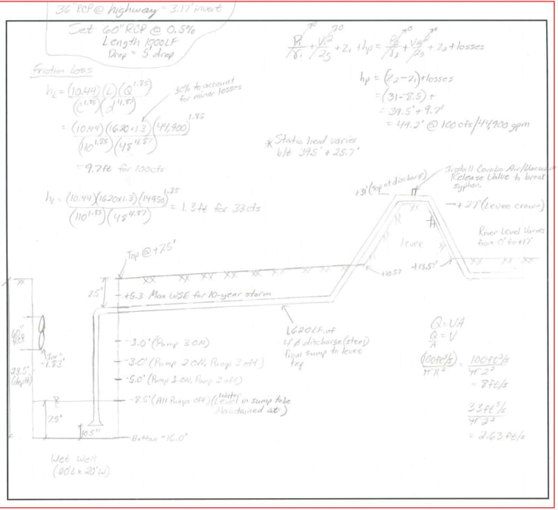
I attached a sketch of the proposed system. The end of the discharge pipe will vary from being submerged to unsubmerged depending on the river stage at that time.

The client wants to use a centrifugal submersible pump like they have used on other stations in the area. The pump vendor is saying the pumps function better with the more head they have to pump against. So it might actually benefit me to use the levee crown elevation in my static head calc. On the other pump stations already constructed that have a similar set of conditions, a vacuum/air release combo valve was used at the levee crossing.

The water level in my wet well will also vary but needs at least 7.5' of minimum submergence. I will set this as the all pumps off elevation. Should I use this elevation in my static head calc?

Pump_Station_Sketch_wpf6dr.jpg
 
I would ask for a meeting with client and pump vendor's engineer, NO salespeople, to talk specifically about the potential for 50% power savings by using a properly selected pump and VSD controls, on all pumps if you will use all pumps when the river is high. I would suppose yes to that. I believe what sales has told you is, shall we say "not exactly correct". I don't know of any client that would not want to talk about savings of up to 50% on power costs.

Yes, looks like 31'leeve top - 7.5' pump suction = 23.5' head + any adders for elbows and pipe friction.
 
The thing with these sorts of systems is that you have a huge volumetric flow range to work with and several issues to address.

We have no idea if these pumps and flows are such you pump 10% of the year or 50% or 1%??

I can only guess if this is a drainage from a highway that inflow is highly variable.

Issue 1
At low flow you need to maximise the length of time that your one pump can run for between high set point and low cut off switch. This really needs to be at least 5 minutes to prevent rapid on/off operation of your pumps and is a balance between volume of the pit and flowrate of your first pump. Often you need a small initial pump flow to give you that time. a medium flow pump second and then a 1:10 year storm pump for the third one.

Issue 2
At high inlet flow your inlet head into the third and biggest flow pump is actually possibly a lot higher than pump 1 and hence in these sorts of low head scenarios you risk oversizing your pump.

Issue 3
The pump vendor wants to sell you the biggest pump he can persuade you to buy as it makes him the most money. Listen to vendors for sure, but always remember that.
You do have the potential here to significantly reduce the power of the 2nd and 3rd pumps taking advantage of the syphon effect created by the first pump. That pays off in lots of ways including motor size, cables, switchgear and power supplies.

Issue 4
At the high point level you have, syphoning shouldn't be an issue of you have some non return valves in the line.

Issue 5
Your set points look very low and short distance to me.
You want to have the ability to have a large time frame for pump operation to prevent short cycling. So pump 1 lift as high as you can, then pump 2 then pump 3 at just below the max liquid level.
Then stagger the off points so pump 3 stops first, then 2, then 1.
Sometimes if pump 3 starts, pump 2 stops unless the water level keeps rising then all three go flat out.
You need to think very carefully about different inflow scenarios and how this would work.

Issue 6
This is not a simple pump out of a pit with fixed levels. It is a transient, highly variable water pumping issue and is more complex than it might first appear.

Remember - More details = better answers
Also: If you get a response it's polite to respond to it.
 
Hello everybody:

ccc89, I am about to undertake a project very similar to the one that you expose in the Forum. I wonder if you could provide me with the name and email address of the pump seller (vendor) and establish a first technical commercial link with him.

Thanks in advance.

El que no puede andar, se sienta.
 
ccc89,
Just some tips, that might be handy:

- The syphon effect will be available only when the down going pipe is entirely filled with liquid (entire cross section). This might not be the case with 1x pump running, having the down going pipe designed for 3x pump running.

- Check the system not only for 3x pump, but also for 1x pump and 2x pump, with the pump curves of the offered pumps. Changes in flow regime and falling away of the syphon effect can have a considerable impact.

- In case you decide to add a "vacuum breaker", which I think is better not to apply, it will have to suck in a lot of air with 3x pump running to break the syphon entirely.

Good luck.
 
Status
Not open for further replies.

Part and Inventory Search

Sponsor