Continue to Site

Eng-Tips is the largest engineering community on the Internet

Intelligent Work Forums for Engineering Professionals

  • Congratulations waross on being selected by the Eng-Tips community for having the most helpful posts in the forums last week. Way to Go!

Pure Bending

Status
Not open for further replies.

MatthewM23

Structural
Oct 5, 2015
5
I am trying to model an open thin walled square beam (as a control) under pure bending in abaqus to validate some research. I have set the material properties up to replicate perfectly plastic behaviour but my results for the Moment at the reference node vs. displacement are those shown in the attached image. Theoretically I should be getting as close as is possible to one sharp kink and taper, however it appears I am getting multiple kinks and a much higher ultimate capacity than what is theoretically predicted.
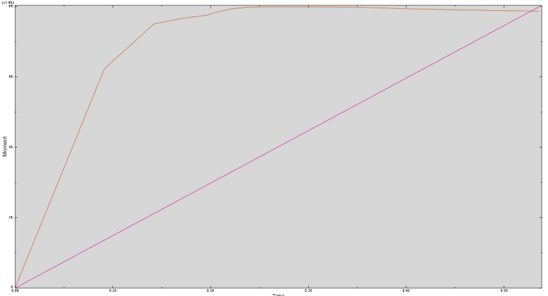
Plot_1_hppq0s.png


Any idea how I might rectify this?

I have performed the analysis by creating a step in the boundary conditions at the two reference nodes at either end of the beam (imposing a rotation).

Also when I probe a cut of the section the stress values on the top and bottom of the beam are much higher then the maximum stress at the top of the linear stress distribution on the side walls - can someone explain this?
 
Replies continue below

Recommended for you

Hello,
In order to get pure bending you might wanna release on of the supports in z-direction ("Also when I probe a cut of the section the stress values on the top and bottom of the beam are much higher then the maximum stress at the top of the linear stress distribution on the side walls - can someone explain this?"). If you dont, you get bending+tension.

If you calculate plasticity (ideal plastic) through the entire cross section by hand, it might be worth turning NLGEOM off since it will take into account local buckling (like the axial crushing example in the example manual).

I re-ran the model with those settings and denser sampling (maximum time step = 0.01) and got a nice curve.
I also turned off stabilization in the step so I wouldnt have to worry about energies.

I dont think you will get a sharp corner on the moment curve since the cross section will gradually start to go plastic.
You will however see a sharp corner (like the stress-strain curve) if you do the same test for pure tension since the entire cross section will go into the plastic region at one increment.

Limit analysis with elastic ideal plastic material curve is described in ASME VIII Division 2. It states that it shall be based on small deformation theory (NLGEOM = OFF?).

Let me know if I interpreted your query correctly. Good luck!

Bending
Bending_eevhrj.png


Tension
Tension_l1wawf.png
 
aslfd,

Thanks for uploading that model with the modified boundary conditions. Why did you choose the one you did? And I am trying to get results w/o the effects of local buckling that is why I imposed the extra boundary conditions on the faces to prevent displacement.

StefCon,

I will see if your solution rectifies this. Addtionally I didn't quite understand what you meant:
"In order to get pure bending you might wanna release on of the supports in z-direction ("Also when I probe a cut of the section the stress values on the top and bottom of the beam are much higher then the maximum stress at the top of the linear stress distribution on the side walls - can someone explain this?"). If you dont, you get bending+tension."

What I am trying to say is that the stress at for example step 6 at the corner (S22) is 262.25MPa and the stress on the top plate at the same location (S11 - which is in the same direction as S22 as measured from the top plate) is 298.44MPa. Shouldn't they be the same.

Thanks for your help guys. Hopefully these changes make a difference.

 
StefCon,

Those changes worked great for my control beam.

I am now having difficulty with my modified beam (much more complicated geometry). I am using similar settings to the ones you suggested but I am getting results which do not correlate with theoretical results. Naturally I don't expect these to be perfect but I am unable to explain the difference.

The theoretical elastic moment capacity has been calculated based on simple beam theory and the section modulus of the modified section (with the outer most fibre at yield). The plastic moment has been theoretically calculated with every part of the section achieving its yield. The corners which have been bent have a much higher capacity (462) in comparison to the 262MPa of the steel in general.

Is anybody able to explain the difference?
 
Hello,
I dont have CAE installed here so I cannot check the model.

About the value difference on top and bottom:
This section in the manual might explain it better than I can (5.1.1 Shell thickness and section points)
[URL unfurl="true"]http://50.16.225.63/v6.14/books/gsk/default.htm?startat=ch05s01.html[/url]

When you use shells you often see stresses as top, bottom or max of top & bottom as options in the post processor. Maybe one could render the shells with thickness and it would be apparent?

If you use small deformation theory, the BC's you had on the side of your control beam could be removed I think.

"In order to get pure bending you might wanna release on of the supports in z-direction."

As I remember (forgive me if I am mistaken) both supports of the control beam were fixed in space (translation x,y,z). If they are fixed like that, the bending you apply will cause bending of your beam but it will also cause indirect tension. Check the average force in a cross section of the beam. If it is zero then there is only bending.

About the results being as your hand calcs I cannot comment on. I didn't check your model in and out and I havent seen your calcs.

Good luck!
 
Hello MatthewM23,

Pure bending is an elastic solution. For me, you don't need a plastic behavior. But if you want to use the plastic behavior of material, I would advise you to use the linear plastic (ex 262 0, 282 0.1) it' s better for elasto-plastic simulations.

You may improve your boundary condition
main1377x.png

The surfaces defined by r = ri and r = ro are traction free.
The surfaces defined by θ = ±α though is subjected to a moment, M along the z direction, has no net force.
Ps :in your CAE, z direction represented by y direction

Good continuation
 
Status
Not open for further replies.

Part and Inventory Search

Sponsor