Continue to Site

Eng-Tips is the largest engineering community on the Internet

Intelligent Work Forums for Engineering Professionals

  • Congratulations cowski on being selected by the Eng-Tips community for having the most helpful posts in the forums last week. Way to Go!

Purpose of grid drawings 3

Status
Not open for further replies.

Azzazil

Automotive
Feb 1, 2020
98
Unfortunately I was not able to make this question on thread Link, since it is closed.
I am curious why in automotive there are drawings with grid and without any dimensions on them?

grid_drawing_x0wgc3.png
 
Replies continue below

Recommended for you

That's a rather simple layout drawing. So in the olden days on one wall of the drafting office there was a full size section through the car, with a 4" grid on it, and all the major components and the driver and passengers all in place. Then you fiddled around with all the bits until they fitted and met your requirements.

These were then used to generate various servicing, shop and repair manuals, like this one


Quite what use your example is to anybody other than model makers, I'm not sure.

Cheers

Greg Locock


New here? Try reading these, they might help FAQ731-376
 
What you show is an example of coordinate dimensioning, where the values (dimensions) are relative to the 0.0 origin in the X, Y, and Z directions. Commonly used in automotive and aerospace to reflect relative position in an assembled context.

"Know the rules well, so you can break them effectively."
-Dalai Lama XIV


edit: what Greg said...
 
here's the sort of thing you'd see pinned to the wall, except they've dimensioned it rather than using grid


and here's one using grid


Incidentally when we talk about hardpoints we often still refer to coordinates referenced to these grids as 'grid', as opposed to whatever LFOR the component is drawn in.


Cheers

Greg Locock


New here? Try reading these, they might help FAQ731-376
 
Thanks for your reply. What is with the drawings for separate component on car like panels or other parts? There I have also grid relative to 0 (center point in car zero) in X,Y and Z direction , but without any proper dimension of thickness and size/position of the holes on the part.

Here is example

grid_second_xggesd.png


Can this kind of the drawing be considered as production drawing? Or the purpose of this drawing is just to show relative position of the part and overal dimensions of the part which you can read from the grid?
Sorry for my ignorance but I never saw mention of this kind of the drawing in GD&T standards as ASME Y14.5 and ISO 1101.
 
Um - what? Is there some concern that those airplanes, trains, ships, cars, and thousands of other items built before 1960 or so sprung out of thin air? Clothing patterns for fabric are still done this way. No Y14.5 in sight.

It is a drawing that is used to create parts. It's not a part acceptance drawing - it's a drawing that would be used by tooling engineers and tool makers to create the dies to create the parts. Those would be used for prototype tooling which would then make prototype parts and then the corrections to fit all the parts properly would be identified and incorporated into the tooling and fixtures for production.

Next question, no doubt - how did the Great Pyramid get built before laser levels were available?

Oh the mysteries of the past!
 
3DDave said:
It's not a part acceptance drawing - it's a drawing that would be used by tooling engineers and tool makers to create the dies to create the parts.

Thanks 3DDave you are helpful as always. Don't mind me for stupid question, what info from this drawing can take tooling engineer since there are no any dimensions on it and tolerances, that can clarify to tooling engineer which features are important and thier precision during production of die?
 
There has to be another drawing of the part with details (dimensions). The grid drawings are nice if you only need to know where something is located.
 
3DDave said:
Here's a bunch of videos to tools that, like grid drawings, you will never have to use:

[king]

That is why I am asking. I saw one drawing from one of our supplier that had those grids and I was confused since I saw it for first time, I was thinking that it was part of some kind of automotive standard.
If this kind of the drawing is oboslete or is not used anymore I won't bother myself to figure out why supplier send us drawing of one part with the grid.
 
Grids are still common today. Dims are charted rather than placed in a view bc they're variables. On a truck assembly print the same rear bumper might have 25 different positions due to wheelbase variations, so its easier to have one print with a chart showing the variations rather than multiple prints. Similarly, on a frame print the "same" hole or other feature might have 25 different locations bc of different wheelbases.
 
3DDave said:
Rather than asking your supplier?

If I am able to ask them I would ask, since I am not I am asking here.

CWB1 said:
Grids are still common today. Dims are charted rather than placed in a view bc they're variables. On a truck assembly print the same rear bumper might have 25 different positions due to wheelbase variations, so its easier to have one print with a chart showing the variations rather than multiple prints. Similarly, on a frame print the "same" hole or other feature might have 25 different locations bc of different wheelbases.

[thumbsup2]

In this case can I consider usage of grid when I want to show position of part on the car, and for the parts that can have different positions in assembly since you mention bumper which can have 25 different positions due to wheelbase?
 
That's too bad. I've never had a case where drawing just showed up and there was no one to ask what they were for. I assume they also didn't ask that you do anything with them and so you can safely ignore them. Tell your boss that you will just ignore them.
 
3DDave said:
That's too bad. I've never had a case where drawing just showed up and there was no one to ask what they were for. I assume they also didn't ask that you do anything with them and so you can safely ignore them. Tell your boss that you will just ignore them.

I agree, but I don't care about my boss and will he ignore them or not. It is important to me to understand them, beacuse I want to know what is their purpose and when they are used.
 
I can only tell you what they were used for. Only the one who made that drawing that you have can tell you why they made it and since you won't find out from them you will never know.

I am beginning to think they sent it just to annoy you and it is working.
 
I said to you I am not able to ask them and I don't have time in detail to expalin to you how that happen. Anyway if you can tell for what they are used for, it would not help only me but also other members of this forum when they will search for purpose of grid drawings.
 
Let's try this:

Why can't you tell me why you don't have time to explain how you cannot ask? I need to understand how you have this problem. It will help me and help other members of this forum to know why this is a problem for you.
 
I came recently in company, and I was checking documentation of some parts and found a drawing with grid lines. When I asked my colleagues why this drawing have grid lines, they told me that they don't know, they just accepted it as that and save it in documnenation database(as you said they just ignore them). Since this drawing was sent to us 5 years ago, we are not in communication with this supplier, and at the moment doesn't make sense to pop-out and ask them for the grid on the drawing.

Anyway I googled and manage to find maybe the defintion and purpose of those grid lines on the internet.

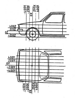
Starting from the axes of this coordinate system, grid lines are spread out parallel to the axes.
These grid lines, spaced 100 mm apart, theoretically penetrate the vehicle. These grid lines serve
to find all points on the vehicle. In other words, they help to determine the position of each vehicle
component. Dimensioning is also performed with the aid of these grid lines.
 
That's what those values on the X and Y and Z axes in algebra when graphing functions were all about, to show the dimensions of the curves at various locations. I think a refresher on how graphing works is in order for your co-workers.

Had you looked at the link to the old tools, one of them is to scale dimensions from drawings like this. specifically.

Also, and this is important, quotes from other websites should have the link to the website.
 
Status
Not open for further replies.

Part and Inventory Search

Sponsor