Follow along with the video below to see how to install our site as a web app on your home screen.
Note: This feature may not be available in some browsers.

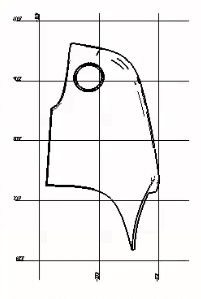
3DDave said:It's not a part acceptance drawing - it's a drawing that would be used by tooling engineers and tool makers to create the dies to create the parts.
3DDave said:Here's a bunch of videos to tools that, like grid drawings, you will never have to use:
![[king] [king] [king]](/data/assets/smilies/king.gif)
3DDave said:Rather than asking your supplier?
CWB1 said:Grids are still common today. Dims are charted rather than placed in a view bc they're variables. On a truck assembly print the same rear bumper might have 25 different positions due to wheelbase variations, so its easier to have one print with a chart showing the variations rather than multiple prints. Similarly, on a frame print the "same" hole or other feature might have 25 different locations bc of different wheelbases.
![[thumbsup2] [thumbsup2] [thumbsup2]](/data/assets/smilies/thumbsup2.gif)
3DDave said:That's too bad. I've never had a case where drawing just showed up and there was no one to ask what they were for. I assume they also didn't ask that you do anything with them and so you can safely ignore them. Tell your boss that you will just ignore them.
Starting from the axes of this coordinate system, grid lines are spread out parallel to the axes.
These grid lines, spaced 100 mm apart, theoretically penetrate the vehicle. These grid lines serve
to find all points on the vehicle. In other words, they help to determine the position of each vehicle
component. Dimensioning is also performed with the aid of these grid lines.
