Continue to Site

Eng-Tips is the largest engineering community on the Internet

Intelligent Work Forums for Engineering Professionals

  • Congratulations IDS on being selected by the Eng-Tips community for having the most helpful posts in the forums last week. Way to Go!

Purpose of tie beam to pile cap 2

Status
Not open for further replies.

dccd

Civil/Environmental
Feb 19, 2021
150
What's the purpose of tie beam to pile cap ?

I was told that When the pile is overloaded, the tie beam from to the next pile cap can help to overcome the problem, When the pile is overloaded, it simply means that the axial compression on the pile is too high How can tie beam overcome the problem? The rebar of the tie beam is to provide some sort of moment resistance I guess?

But, again when the pile is overloaded, the main purpose is to reduce the axial load on pile. How can providing tie beam reducing the axial load on pile?
 
Replies continue below

Recommended for you

Yes, but I like to see some method to the madness. It does seem the ACI paragraph that Koots posted has something to say about beams in proportion to a minimum M and V. Is it SOP these days? In everyone's design procedures or what?

 
I think you'd need at least simplistic FE modeling to prove it, that looks like what bones did
 
1503-44 said:
There's something that still bothers me about designing tie beams for distributing loads across weak piles. Is this something that is done on a routine basis?

I think it depends on the region. I imagine this system is used a lot in places with poor/variable soils and on the higher end of the earthquake risk spectrum.

1503-44 said:
Bones206, One other question if I may. What span lengths are you using between piles?

The short span is 5 ft and the long span is 10 ft.

1503-44 said:
And I assume the tie beams are 24" high, 18" wide?

Correct.

1503-44 said:
If I include the weight of the tie beam, the center pile load is 43% higher at 48K.
Does that sound right? That's the part that seems counterproductive, but that is from the entire tie beam load, not just the extra bit you need to add to make it stiff enough to span.

I set the beams to be weightless in the model for illustration purposes, but in reality some of that weight would end up in the piles. The relative percentage of beam weight being taken by the piles probably depends on the subgrade modulus. In my model, I set the subgrade modulus to zero, but in reality the soil could be taking a significant amount of that beam load. And if the soil is stiff enough to take some of the beam load, it means it can also help reduce settlement to some degree.
 
bones206 said:
Here's an example using RISA:

- 3 equivalent piles with 50 kip load (red arrows)
- 24"x18" continuous grade beam connecting the 3 piles (density set to zero for this example)

Results show, as expected, each pile has a 50 kip reaction (green arrows):

thanks for the example. But , it seems that the tie beam is to reduce the settement, but in actual case, how deos the tie beam overcome the oeverloading of pile when the ECC is small (column loading is closer to the overloaded pile instead of the new pile, means that the pile is still overloaded after adding the tie beam ) ? Or is there any better to overcome the overloading of pile ??
 
1503-44 said:
SOP these days? In everyone's design procedures or what?

1) I'd never even heard of this until I found it myself, rooting around in the literature.

2) Thus far, I've yet to encounter anybody other than me doing this.

3) I'm using this procedure but only in select contexts.

a) Interior columns spaced 30' in institutional buildings? Nope, mostly hopeless. I would do a raft first usually.

b) Exterior columns in all buildings on façade lines? Yes, I feel that it's wise for façade performance.

c) Any pile under a basement wall? Moot as the wall does this job.

d) Small scale setups like helical piles where the beam depths really are meaningfully stiff relative to the piles and pile spacing? Yes.

4) In my opinion, the strength requirements are primarily indirect stiffness requirements.
 
For clarification when you say - "...closer to the overloaded pile instead of the new pile, ..."
are you looking at an existing system and trying to reduce the load on an existing in place pile? If so then a tie beam will do basically nothing.

If this is a an entirely new system then:
First understand that piles are not rigid supports, in my experience the pile capacity is based on an allowable settlement value. Give the capacity and allowable settlement the pile can be modeled as a vertical spring with stiffness = P,capacity/settlement

If the tie beam is sufficiently rigid then a load directly over a pile spring may redistribute out to adjacent pile springs connected to the tie beam.


My Personal Open Source Structural Applications:

Open Source Structural GitHub Group:
 
Celt83 said:
First understand that piles are not rigid supports, in my experience the pile capacity is based on an allowable settlement value. Give the capacity and allowable settlement the pile can be modeled as a vertical spring with stiffness = P,capacity/settlement

thanks, I just knew this. Can I say that the tie beam is to reduce the settlement. Hence, when the settlement is reduced, the spring stiffness will be higher and the pile can take more load, (pile caapcity is now increased , and wil not overstress ) ??
 
Bones, thanks very much. Yes, there probably is some regional practice and previous experience on pile performance in there. I used much longer spans, hence the high load from the beam weight at the center pile. Even with longer spans awith beam weight =0, the loads distributed to the piles were essentially the same as the Risa analysis. Mostly influenced by pile stiffness and keeping beam EI/L proportional I suppose. My spans were of similar ratios.

Geotechguy1, I got Excel to within a few percent of Rise results just using superposition and 6 iterations of the full span calculating deflection at loading point above the central pile against the pile's deflection and load stiffness factor. Doug Jenkins' blog at
does some great structural work with FEA using Excel.

dccd,
The beam stiffness is considered, which distributes that load away from the weak support.
 

Can you explain how does the tie beam in overcoming the settlement and overloading of pile in more detail please ? I am still confused. [ponder]

Or in this way ? Since the spring is constant , providing a tie beam between them can reduce the settelement, and hence, the pile capacity will incerase as the spring is constant ? (Spring = Pile capacity/ settlement )
 
I suggest you find a good book on the stiffness matrix methods, here is a good free one: Link - MASTAN2

First using Bones206 example:

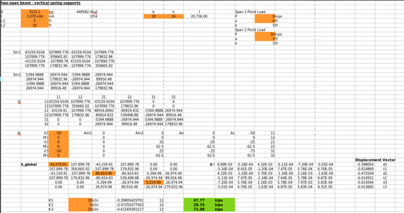
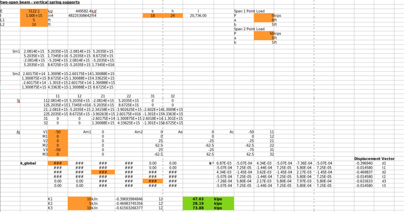
For the 24" (tall) x 18" (wide) beam assuming F'c= 3000 psi and no stiffness reduction
Code:
E	3122.1	ksi	449582.4 ksf
I	20736	in4	1	 ft4
L1	5	ft		
L2	10	ft

For all of the below matrices length has been taken as feet for consitency
The stiffness matrix for the 5 ft span beam is:
Code:
43159.9104	107899.776	-43159.9104	107899.776
107899.776	359665.92	-107899.776	179832.96
-43159.9104	-107899.776	43159.9104	-107899.776
107899.776	179832.96	-107899.776	359665.92

The stiffness matrix for the 10 ft span beam is:
Code:
5394.9888	26974.944	-5394.9888	26974.944
26974.944	179832.96	-26974.944	89916.48
-5394.9888	-26974.944	5394.9888	-26974.944
26974.944	89916.48	-26974.944	179832.96

The global system stiffness matrix inclusive of the Pile Springs is, Kglobal:
Code:
43279.9104	107899.776	-43159.9104	107899.776	0	0
107899.776	359665.92	-107899.776	179832.96	0	0
-43159.9104	-107899.776	48674.8992	-80924.832	-5394.9888	26974.944
107899.776	179832.96	-80924.832	539498.88	-26974.944	89916.48
0	0	-5394.9888	-26974.944	5514.9888	-26974.944
0	0	26974.944	89916.48	-26974.944	179832.96

Because we are looking at this as a 2D problem and the vertical supports are springs then all joint displacements are unknown, and we know the joint loading is 50 kips at each joint. P*Kglobal^-1 = delta
Kglobal^-1:
Code:
0.005974863434211	-0.000490054673319	0.003537704848684	-0.000482185804678	-0.001179234949561	-0.000466448067397
-0.000490054673319	8.33763749299879E-05	-9.82513233548591E-05	7.38899760184168E-05	0.000588305996674	6.60386099950961E-05
0.003537704848684	-9.82513233548595E-05	0.003026776060308	-0.000110054626316	0.001768852424342	-0.000133661232237
-0.000482185804678	7.38899760184169E-05	-0.000110054626316	7.5498754980889E-05	0.000592240430994	6.75948811060119E-05
-0.001179234949561	0.000588305996674	0.001768852424342	0.000592240430994	0.007743715858553	0.000600109299635
-0.000466448067397	6.60386099950961E-05	-0.000133661232237	6.75948811060119E-05	0.000600109299635	8.1828855127665E-05

resulting Delta vector, deflection is in ft for consistent units:
Code:
0.416666666666683
-8.74300631892311E-16
0.416666666666678
-9.22872889219661E-16
0.416666666666669
-9.5062846483529E-16

From spring definition we know P=k*delta --> K=10 kip/in * .416666666 ft * 12 in / ft = 50 kips @ each spring

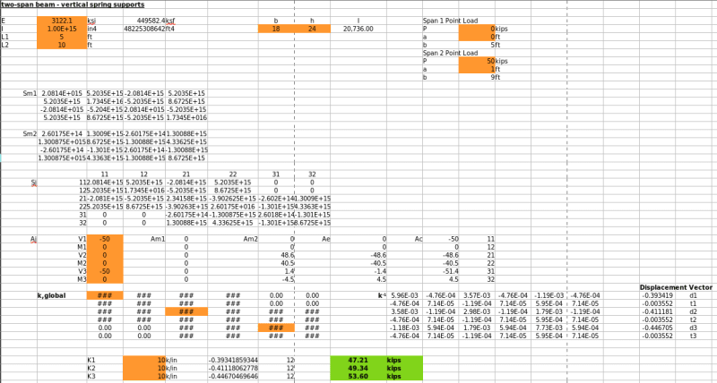
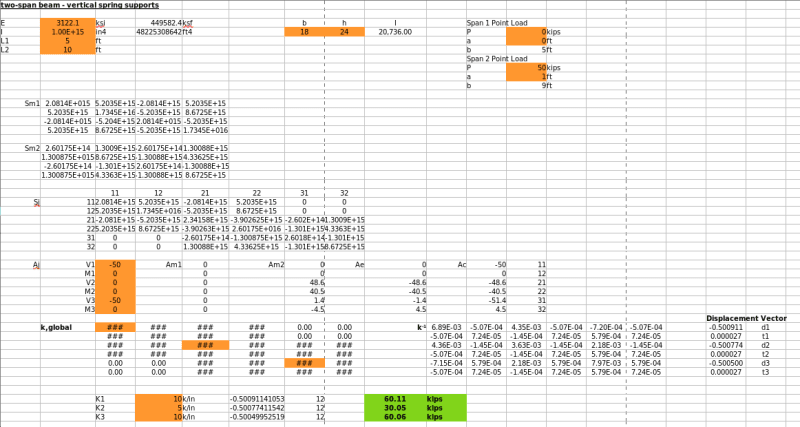
Setting the central spring to K=5 kip/in

k,global becomes:
Code:
43279.9104	107899.776	-43159.9104	107899.776	0	0
107899.776	359665.92	-107899.776	179832.96	0	0
-43159.9104	-107899.776	48614.8992	-80924.832	-5394.9888	26974.944
107899.776	179832.96	-80924.832	539498.88	-26974.944	89916.48
0	0	-5394.9888	-26974.944	5514.9888	-26974.944
0	0	26974.944	89916.48	-26974.944	179832.96

and the Delta vector becomes:
Code:
0.524735252368115
-0.003001347487258
0.509127576229035
-0.003361910708932
0.470700959517384
-0.004083037152281

Which produces the following reactions:
R1 = K1*delta1 = 10 kip/in * 0.52473... ft * 12 in/ft = 62.9682 kips
R2 = K2*delta2 = 5 kip/in * 0.50912.... ft * 12 in/ft = 30.5477 kips
R3 = K3*delta3 = 10 kip/in * 0.47070... ft * 12 in/ft = 56.4841 kips

My Personal Open Source Structural Applications:

Open Source Structural GitHub Group:
 
to expand on that calculation:
- Shear deformations where not included, that will soften the beam

-!! with equal springs and loads applied at the springs the beam has no impact to the reaction distribution.

- In real life conditions will rarely match the idealized analysis model, so there may be pockets of poor soil which would impact the pile settlements and that is where the tie beam would really be helpful in limiting the relative pile settlements so that the differential settlement is within a tolerable range for the structure above.

My Personal Open Source Structural Applications:

Open Source Structural GitHub Group:
 
Further to some of Celt's points, it is equally probable that, with tie beams:

1) A given pile may see its load demand reduced as load is distributed to adjacent piles and;

2) That same pile may see its load demand increased as adjacent piles distribute their load back to the pile being considered.

In conventional situations, this strategy is viewed as a way to generate some level of system behavior from a collection of discrete components. It's not unlike how, with shallow strip footings, we rely on the stiffness of the footing and stem wall above to span over potential soft spots in the supporting soil.
 
To address your "small" and "large" eccentricity question.

"small" eccentricity - constant springs and same beam as previous example
Screenshot_from_2021-06-21_14-27-17_ggi6l0.png


as above with a very very stiff beam
Screenshot_from_2021-06-21_14-28-57_r6rgwl.png


"small" eccentricity - interior spring = 1/2 K
Screenshot_from_2021-06-21_14-32-09_yrn8wd.png


as above with very very stiff beam
Screenshot_from_2021-06-21_14-33-54_fyceoo.png


"Large" Eccentricity - interior spring = 1/2 K
Screenshot_from_2021-06-21_14-40-23_syy30j.png


as above with a very very stiff beam
Screenshot_from_2021-06-21_14-41-19_aefywx.png


For the small eccentricity cases you can see how the "very very stiff" beam case really works to equalize the displacements. However for the large eccentricity case you can see how no matter how stiff we made the beam the load distribution doesn't change much.

My Personal Open Source Structural Applications:

Open Source Structural GitHub Group:
 
Status
Not open for further replies.

Part and Inventory Search

Sponsor