Eng-Tips is the largest engineering community on the Internet

Intelligent Work Forums for Engineering Professionals

Qestion about user SIF on Caesar II

Status
Not open for further replies.

nux

Mechanical
May 3, 2024
6
0
0
TR
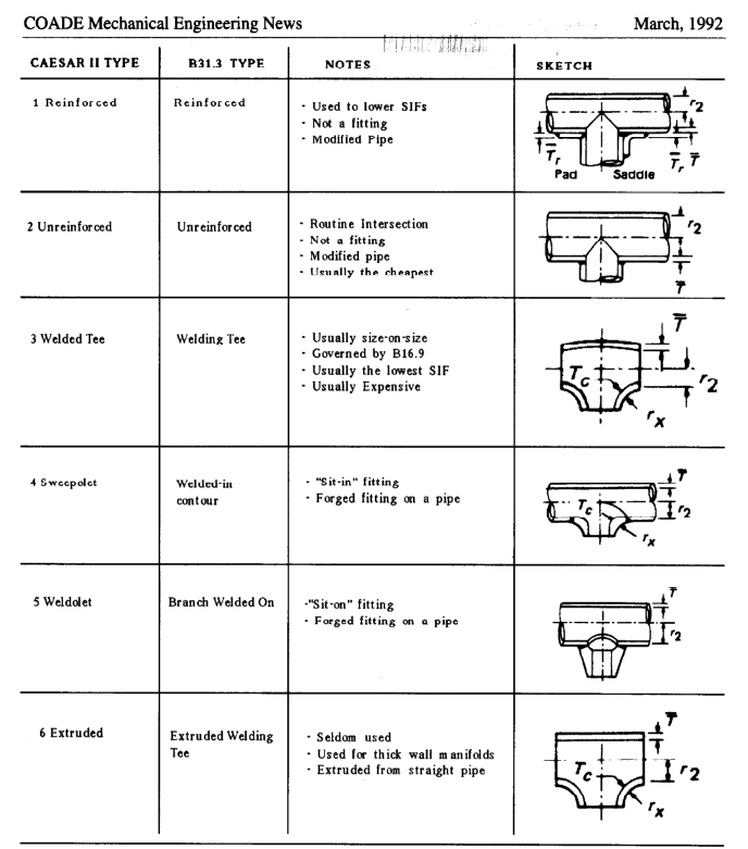
Hello everyone, my question is about user defined Weldolet SIF on CaesarII. My header size is 28" STD and branch size is 12" S40. When i let the caesar calculate sif values and run the analysis i dont have any issue on stress ratios. But when i enter the same sif values manually(User SIF) which calculated by caesar i get problem with stress ratios and bending moment value increases a lot. Let me explain how i enter sif values manually.

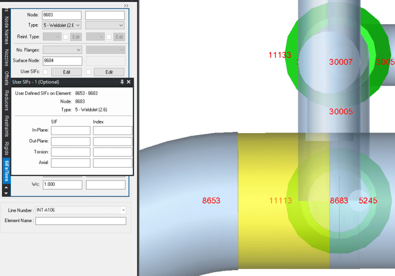
Below screenshot from the analysis which i let Caesar calculates the SIF values automatically. As you can see Caesar creates node on surface which is 8684. Second screenshot shows stress and sif values from analysis which i enter sif values manually. My user SIF values same with Caesar calculated values but there is huge difference stress ratios and as you can see bending moment value increased.

1_df3ue2.png

2_hbquzm.png


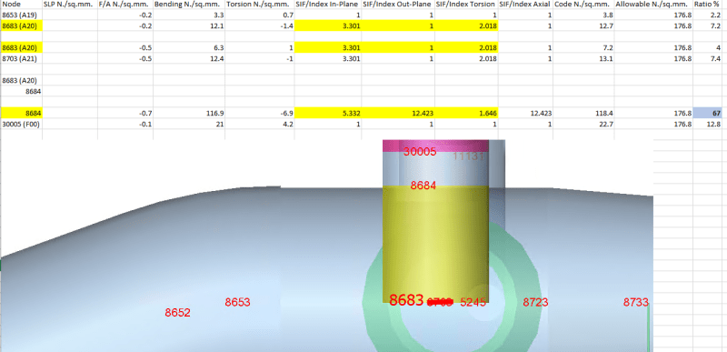
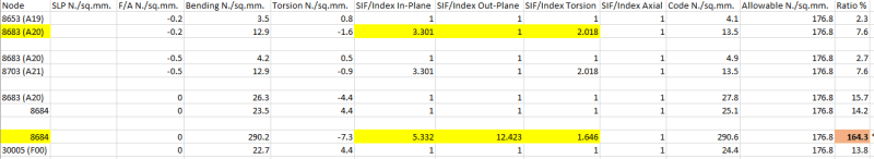
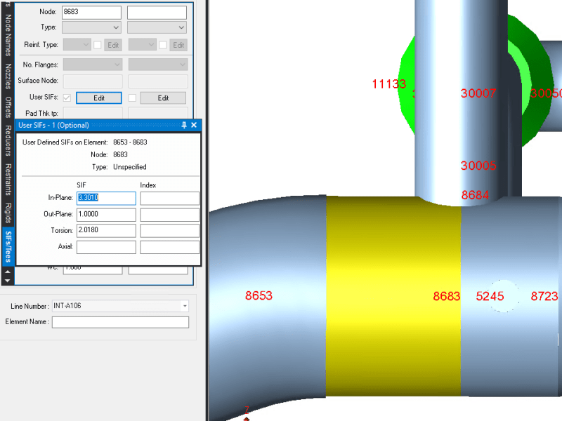
When i enter SIF manually i broke node at surface which is same node number with Caesar creates and i entered same values which are 5.332, 12.423, 1.646. 3rd and 4th screenshot shows USER SIF that i defined and 5th screenshot shows SIF settings which i let the Caesar calculate.

3_h5i9rv.png

4_bmosxe.png

5_kdsbxb.png


When i consider these i believe that i make a mistake with branch connection modelling.

So my question is how should i model this branch connection so i can get same stress results?

Thanx in advance,
Best Regards.
 
Replies continue below

Recommended for you

1) Are you using later versions of the program where its calculating SIFs per B31J? Or are you working on an old system using the old appendix values?
2) If the pipe input parameters (size, schedule, intersection type, etc) match, the SIF scratchpad should calculate the same value I think? I've largely only used that to gut check if changing thickness/intersection type would resolve the stress issue. In your screenshots the type is unspecified - is it unreinforced/fabricated, extruded, what? Your last screenshot appears to say its a 12" olet on a 28" pipe, I just don't buy that's the real scenario.

Here's an image from the old Coade articles that may help you pick the appropriate intersection type if you don't know.

Lastly, at these sizes, its very possible regardless of your intersection type that Caesar will be overly conservative. This is because Caesar II is not FEA , everything is just a stick with varying degrees of stiffness. If you go thru everything and still have stress issues, you may need to run an FEA analysis on this intersection to get real stresses.
Tees_b5qjwj.png
 
Firstly thank you for answer.

1) I use V13 and program calculates SIFs per B31J.
2)The reason of the type is unspecified is that i use user defined SIF(these SIF values are same with what scratchpad calculates). When i select connection type, it ignores my user defined SIFs. For your first sentence, i enter same SIFs values what SIF scratchpad calculates. Thats why i would expect same results from 2 analysis but as i said when i define same SIFs values what C2 calculates for weldolet connection, i get different results.

Also i got SIF values from FEA results and these values are lower than SIF Scrathpad calculated values but when i enter these values as branch SIF to node 8684 stresses are increasing with lower SIF values.
 
If you're inputting an SIF from FEA I don't believe the SIF scratchpad will ever match - it's not doing FEA, its doing B31J calculations using those equations. So I'm not sure why you're trying to compare to B31J when you already have a higher resolution number from FEA.

Your screenshots seem to indicate you're defining an intersection at both 8683 and 8684...not sure why you're doing that unless its a part of the FEA output.

I suggest creating a Hexagon smartdesk ticket and asking them to resolve it.
 
Firstly thank you for all answers and helps. However i think the topic is going somewhere else than what i try to explain. Basically i try to learn how to define USER SIFs for weldolet connections. Because when i define SIF vales what Caesar calculates, i get different results with same SIF values.
 
I think what happened is as follows:

When caesar calculated the SIF as in the first screenshot at top it considered the element from the 8683 to 8684 to be a massless rigid element. Modeling in this way accurately put the location of the stress intensification at the surface of the pipe and eliminated the pipe section between the surface of the pipe and centerline of the pipe. This method of modelling is described in the attachement of my previous post. This is why it is of a goldish color and why on the stress output sheet there is no stresses shown for that element. Stresses are only shown at the end point of the element 8684.

When you modeled it I believe you modeled the element between 8683 and 8684 not as a rigid element but as a regular pipe element. You can see that the color is blue of this element on your screenshot and that on the stress report there is now stress values given for this element which indicates it is not modleled as a rigid. This form of modeling changes the stress values since it adds 14" of extra pipe lenght that really does not exist between the surface and centerline of the pipe.

If you redo your calculation and change the element 8683 to 8684 as a massless rigid the results should come out the same.

 
Thank for the reply.

I tried with rigid element and i got similar results but when i lower size and wall thickness of rigid element stress values decreasing but in this scenerio my question is what should be the size and wall thickness of rigid element?
 
It has been a while since I modeled Caesar and rigid elements. From what I remember there was some relationship between flexibility of a rigid element and diameter of element you input. The larger the diameter the more rigid until somewhere it became absolutely rigid. There should be a discussion in the Ceasar Technical Manual about rigid elements and how to model.
 
Status
Not open for further replies.
Back
Top