Eng-Tips is the largest engineering community on the Internet

Intelligent Work Forums for Engineering Professionals

Question about controlling bow on extruded profile

ndpaintballer

Mechanical
Oct 1, 2024
2
0
0
US
We are trying to control overall bow of an extruded vinyl profile. For a 200" lineal length piece, max of 2" bow is what supplier can control.

IMG_6530_i45dgr.jpg


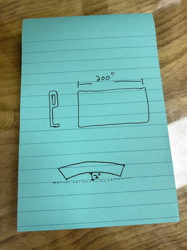
I've added a quick sketch to try and explain better.

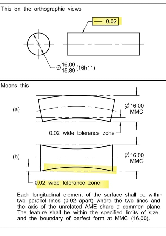
Would a straightness callout on bottom of profile be the best way to call this out? This is assuming that the entire profile bends when that surface is bent and not just that bottom surface.

IMG_6531_sxzqzv.jpg


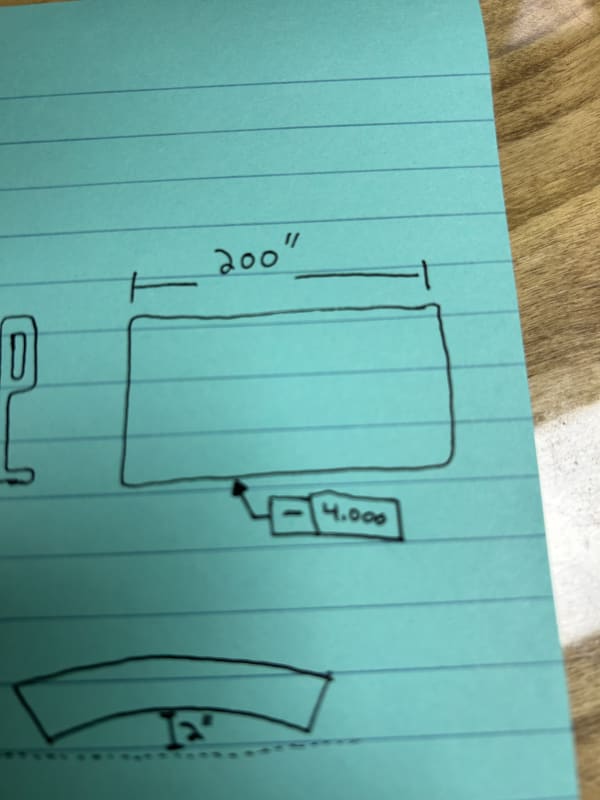
or would profile tolerance be better for this scenario?

Thanks!
 
Replies continue below

Recommended for you

Hi, ndpaintballer:

Well, it depends on how it is used. I can't tell size of the profile from your sketch. An extruded vinyl profile with 200" long can be very flexible. Are you going to inspect it at free state or in a restraint condition?

Best regards,

Alex
 
Straightness of a surface still has to meet perfect form at MMC, so that may not solve the issue. Possibly dimensioning the overall height and applying the straightness to the center plane, which would allow overriding perfect form at MMC.

 
marshell said:
Straightness of a surface still has to meet perfect form at MMC, so that may not solve the issue. Possibly dimensioning the overall height and applying the straightness to the center plane, which would allow overriding perfect form at MMC.

That might be a good suggestion since the OP did say that we are to assume that "the entire profile bends when that surface is bent and not just that bottom surface."

Or another workaround would be to use the I modifier upon the size callout.
 
I think flatness callout is better. Alternatively, OP can control "straightness" using local and overall thickness or height.

Best regards,

Alex
 
Functionally, what do you hope to achieve by restricting the free state to a really sloppy tolerance?

If we imagine that the extrusion is installed with the goal of being straight, then wouldn't it be better to inspect with the edge constrained to be straight, and confirm that other features are whatever they need to be in that condition?
 
The extrusion process tends to produce curvature and twist, most noticeably on asymmetric profiles, depending on how the die is constructed, the material pulled/pushed, the cooling rate of various parts of the section, and any post-extrusion treatments.

Unfortunately ASME Y14.5 doesn't have controls on curvature or twist.

For a given section a limit on curvature and twist applied directly represent the amount of force required to constrain the extrusion to be straight and not twisted; a simple geometric measurement instead of a complicated fixturing requirement. It's the inverse of beam deflection calculations - for a given amount of deflection will the installation force be OK? Control the deflection and one controls the installation force.

All other properties can be section properties and don't require the part to be restrained.

I would be surprised if the allowable deviations had a stress analyst report to justify them, but anything is possible.

I note that ANSI H35.2 doesn't seem to use anything else but similar measurements. An example of the sort of controls H35.2 manages: Not a geometric characteristic in sight.
 
3DDave said:
for a given amount of deflection will the installation force be OK? Control the deflection and one controls the installation force.

Right. If installation force is what's important.

But maybe installed form is important. We don't know, because ndpaintballer hasn't told us.
 
Installation force is always important. Can't be constrained straight without applying force if there is expected to be a large amount of deviation.

Anyway, lacking input from the OP, I was surprised at your suggestion of forcing the part straight to verify it.
 
Back
Top