Eng-Tips is the largest engineering community on the Internet

Intelligent Work Forums for Engineering Professionals

  • Congratulations waross on being selected by the Tek-Tips community for having the most helpful posts in the forums last week. Way to Go!

Question about simulate biaxial reinforced concrete column

Status
Not open for further replies.

adrianuk

Structural
Oct 23, 2018
8
0
0
HK
Hello guys.
I would like to would know how to simulate biaxial bending moment acting on RC column
i.e for a fixed axial load I want to apply time changing biaxial load.
As I want to find the ultimate capacity of the RC column under constant axial load with changing biaxial load.
How do I simulate this forces or get the ultimate capacity of the column.

Thank you
 
Replies continue below

Recommended for you

Not sure, why you want to do this (academic work perhaps), because a relevant concrete code (say EC2) will very often tell you what the moment capacity is for a column with or without axial forces.

Anyway in order to simulate such a complex phenomenon, depending on the level of accuracy and complexity needed one can do:

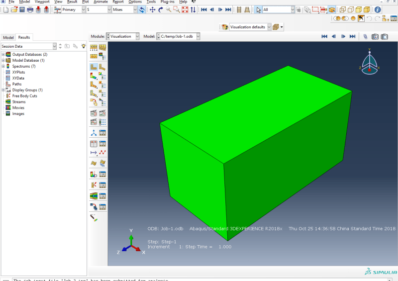
The most complex level would be to model the concrete with brick 3D elements using the concrete damage material models of abaqus for modelling concrete cracking and crushing.
Truss elements would then represent the discrete reinforcement, using a nonlinear elasto plastic model. Of course one could then look at their interaction, which in the simplest case when they share nodes, models when they are perfectly connected.
This video shows how all this could be done Link

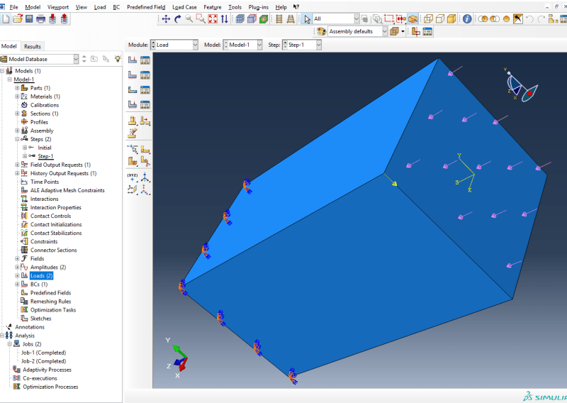
As for the loads one can define several loads (e.g., axial) and moments (+ or restraints) and increase or keep them constant as needed. As you are looking into failure, one might need to use the arc length method (called Riks in abaqus) to capture any softening of the structure (other sub stepping techniques such a load scaling cannot cope with a negative tangent stiffness).

You can then plot a load vs deflection (load-deflection) curve to see how it behaves.

This is a summary, and it might sound easy, but it is fairly complex, so to do this it depends what you want to achieve.
(If for design purposes then using the codes, or dedicated concrete design software might be way more efficient)


Of course, since this is fairly complex it is even more important to verify and validate the results (perhaps even with physical testing).

 
No worries.

For the time varying load you can do it via an amplitude curve. See *amplitude keyword or in the cae go to:
Load or Interaction module: Tools/Amplitude/Create

As for the constant load you could do that also (define a curve with time 0 amplitude equal to axial force in N and at 10 it has the same value, so just a constant curve), or just put a constant value like you wold normally (bare in mind it could be ramped up then).

Once you have that amplitude curve defined you can choose it when defining the moments and forces (under Amplitude drop list, by default it is Ramp).

Have in mind that loads are by default ramped, and that time in a static analysis is a pseudo time, so it is not that it will be a transient dynamic time history analysis, it is still just a static analysis (there is no mass matrix * acc., so no forces due to inertia) with the pseudo time being incremented along the analysis (another way to think of it is a load increment).
 
Thank you agian Erik Panos Kostson.

Because I just start to learn about Abaqus for my project.
I learn how to model a reinforced concrete column on Abaqus.
But I don't quite know how to arrange the loads and make them changing with time.

Here is my trial about setting of load:
For my axial load on tabular
2_wznvww.png


For lateral forces on tabular:
1_meadgq.png


Is that correct? However, I tried this setting on just a rectangular solid, it just showed Step time = 1
4_oh4ubi.png

3_vefoio.png
 
Since you have a pseudo time of 10 you need to set the final (pseudo) time to 10 in your Step definition.
By default it is set to 1.

Then in the Load or Interaction module go to the main menu and Tools/Amplitude/Create, and assign two curves as you show in your excel table.

Once you have that amplitude curve defined you can choose it and assign it to the loads when defining the moments and forces (under Amplitude drop list, by default it is Ramp).

---
New to this forum read the posting guidelines:Link
If you are a student use this link for posting questions: Link
 
Thank you agian Erik Panos Kostson.

What to u mean by "assign two curves as you show in your excel table." Does that mean put the excel table into Tools/Amplitude/Create>tabular ?

Thank you very much. You really help me alot
 
Yes, you need to enter your table values in there (just press enter to create a new row when you are on 2nd row and 2nd column, because there are only two rows in the tabular table; alternatively copy paste your values from excel into the abaqus table). In any way I am sure you will manage to do it, just try it out.

 
Status
Not open for further replies.
Back
Top