Eng-Tips is the largest engineering community on the Internet

Intelligent Work Forums for Engineering Professionals

  • Congratulations waross on being selected by the Tek-Tips community for having the most helpful posts in the forums last week. Way to Go!

question about small submersible pump bhp vs current characteristics 5

Status
Not open for further replies.

electricpete

Electrical
May 4, 2001
16,774
0
0
US
I have a question about Goulds WE0511HH pumps that we use in a sump application: Submersible Pump. 1/2 HP, 115 Volt, 60 Hz, 3.87″ Impeller, 2″ NPT Discharge, 20′ Cord, 3/4″ Solids.

I'm not sure where is the best place to find info on this pump (google floods me with distributors), but here is a link

Question 1: what does the bhp vs flow curve look like? Does bhp increase with flow, or decrease with flow, or increase then decrease with a peak near bep in the middle?

Question 2 (if question 1 is unknown / ambiguous): what is the construction of the pump (axial flow, radial flow, number of stages)?
I think it's radial flow single stage. I’m under the impression single stage radial flow pumps generally have increasing bhp vs flow while single stage axial flow pumps generally have decreasing bhp vs flow.

Background: We have some chronic problems with this pump tripping, often on start, sometimes during run. Historically we have focused a lot on filtering the suction and blamed the trips on debris. We just noticed we have Bussman KTK-15 fast act fuse which we’ll be upgrading to KTK-20 in hopes to solve the problem. Beyond that we’d still like to understand what role is the system operating point (flow resistance) and also the impact of debris that might end up obstructing flow (we immediately neck the 2” discharge of the pump down to ¾” pipe). Obviously if debris jams the pump that would cause trip but I'm just interested in the effect of the operating point on the current. There are other people here involved reviewing other aspectsm but my piece is just the question about effects of operating point effects on current.


=====================================
(2B)+(2B)' ?
 
Replies continue below

Recommended for you

It's a cast iron semi open single impellor so power usually rises with flow, but the goulds manual doesn't give a lot away as the head falls a lot with increase in flow.

Obstructing flow shouldn't cause an overload unless it jams the impellor and you get locked rotor.

The HH bit at the end is High Head and a sample look at some flow number for me says 1/2 hp motor is right on the limit or actually over.

see
The line for the WE0511HH at 115 V states max amps 14.5, locked rotor 46A and max efficiency only 54%.

SO if you're at lower flows, the at say 5m3/hr, its putting out 15m head. Assuming a pump effiency of 0.5 gives me a shaft power of 406W, so 0.53 hp.

The power figures for the two pumps, HH and H are the same which is difficult to believe.

But it could well be that if in fact you're running too fast (can you measure your flow??) then you might be drawing more power than the motor can supply

Remember - More details = better answers
Also: If you get a response it's polite to respond to it.
 
Outstanding, that gives me something I can sink my teeth into. But as always a lot more questions.

> The power figures for the two pumps, HH and H are the same which is difficult to believe

Yeah I'd agree there. 3.56 impeller size for the H version and 3.87″ impeller size for the HH version. My first thought was maybe they were looking at an operating point where the two curves crossed on the figure which looks to be 55 feet and 67gpm from the curve on page 2. But then I scroll to page 4 the table labeled "Performance Ratings" and 55ft is beyond the row where they stop tabulating numbers (beyond shutoff?). They don't tabulate anythign beyond 25ft for the WE05H or 45 ft for WE05HH. It makes no sense to me. Maybe I have mixed my units or something....am I missing something there? I don't understand the relationship of the model numbers on page 4 performance table (example WE05HH) to those on page 2 (example WE0511HH) (I had my part numbers all crossed, sorry).


> But it could well be that if in fact you're running too fast (can you measure your flow??) then you might be drawing more power than the motor can supply

I don't have the nameplate but the motor comes with the pump and the catalog suggests 2-pole motor. We don't have any vfd. I'm not sure how we would be running it too fast.

Another random question, does anyone have any example pump with similar construction from which we might estimate the shape of the efficiency vs bhp flow curve for this pump?


=====================================
(2B)+(2B)' ?
 
Sorry, when I said too fast, I meant too high a flow rate / end of curve. That eats power.

Or what is your operating head / lift / pressure?

Also can you measure the voltage being supplied when it's running? At 115V, if it is actually say 105V when operating you're going to eat amps

For these sorts of small basic semi open impellor pumps you could be way out as fixed issues will be more than the variable ones.

But basically the mfrs skimp on everything to get a pump which sells more than the next one so I think you're just too close to the wire.

BUY A BIGGER MOTOR

Remember - More details = better answers
Also: If you get a response it's polite to respond to it.
 
Since you mentioned replacing the motor, I looked at the literature data again and I am trying to make sense of this: Max amps is listed as 14.5 for a 0.5hp 115 volt motor.

14.5A at 115 volts is 1667 VA
0.5hp is 0.5*745watts is 272 watts.
If that 14.5A corresponded to nameplate hp the product of pump efficiency times motor efficiency times power factor would have to be:
272/1667 = 0.16

Something seems out of whack to me there. Either the pump is ridiculously inefficient (much lower than that 54% stated) or else the motor is going to run way over nameplate horsepower. Is that the way you're looking at it? I guess the motor efficiency and power factor must be pretty low too.

UPDATE – After upsizing the fuse, we started the pump.
It ran for 15 seconds near locked rotor current (40A), then the internal overload tripped.
Then after 20 more seconds the internal overload reset and motor restarted. This time the current dropped faster.. it got to 20A within a few seconds and then 13A within a few minutes.
(Current traces from the above are shown on slides 1 and 2 attached)

We manually stopped the pump and later restarted it. On this start (2nd manual start, 3rd overall start) the current dropped to 13A within a few seconds (slide 3 attached).

Each of these three successive starts seems to be getting quicker as load presented by the pump is decreasing. In addition during the first start there were erratic current spikes. I’m thinking that might represent some kind of debris in the pump which worked it’s way out as these starts progressed.

There certainly may be some motor upsizing in the works but at the moment our focus is understanding what’s going on and short term actions. Considering asking them to inspect the pump for debris.

questions - have you ever seen a current waveform like that first start? do you think it represents foreign material or something else?

=====================================
(2B)+(2B)' ?
 
Pete; Those times are completely out of reason. There is something mechanically wrong OR I'm thinking it's a wiring failure. You have a bad joint somewhere. The motor could be single-phasing intermittently or since it's a pump, actually managing to start eventually and run and not go up in smoke as fast as motors not sitting in 'coolant'.

I'd first check the voltage at the absolute closest you can get to motor.

If it's a single phase motor (and looking back at your OP it probably is) then you have a starting capacitor circuit issue. Either it's failed (likely) or the circuit's switch-in/out wiring is bad.

Keith Cress
kcress -
 
Thanks for your comments Keith.

No doubt the first start was way too slow and the 2nd start (a self-start when I presume the overload reset itself) was somewhat slow compared to the 3rd start. That's why I highlighted those durations.

Yes it is 115vdc

To me an electrical problem does not fit the self-restart. I don't think I explained the scenario well, so let me try to see if I can make it more complete / coherent:

[ul]
[li]t = 0: start the motor (manually). Red light at controller turns on, flow is noted, current goes to 40A.[/li]
[li]t=0 to t=15 sec - current remains near 40A (with erratic spikes every 0.4-0.8seconds shown on slide 1)[/li]
[li]t = 15 seconds. Pump stops (by itself). Current goes to 0. Flow stops. Controller red light remains on.[/li]
[li]t = 15 to t=35 seconds. Current remains 0. Red light remains on.[/li]
[li]t=35 seconds. Pump starts (by itself). Current goes to 40A. Flow is heard.[/li]
[li]t=37 seconds. Current is down to 20A.[/li]
[li]t=1 - 3 minutes - Currents drifts down to 13A.[/li]
[li](everything above is on slides 1 and 2).[/li]
[li]t=10+ minutes. secure the motor (manually).[/li]
[li]Later on slide 3 motor is restarted (manually), current initially goes to 40 amps and then drops to 14amps in 2 seconds.[/li]
[/ul]

I presume the third start (slide 3) is close to what a normal start is. the previous start (self-restart) is abnormal and the first start was very abnormal.

The scenario that makes sense to me is a mechanical problem that slows the motor. The motor internal overload responds as expected by tripping after around 15 seconds of current close to LRC, and then also resets itself as expected 20 seconds later to reenergize the motor. (I'll clarify "as expected" to mean that it sounds reasonable to me, but I need to mention that I don't actually know the characteristics of the motor internal overload for tripping and resetting).

There is also that erratic current after the first start. And the fact that each successive start is a little faster. I postulate maybe these two aspects are explained by some foreign material rattling around in the first start that gradually works its way out. Maybe.

I have a hard time explaining it with an electrical fault of wiring failure or bad joint or cap. It caused the motor circuit to completely open, and then it magically reclosed itself 20 seconds later? Remember also the controller red (running) light stayed on throughout. Does that electrical scenario still seem reasonable to you? It wouldn't be hard to check voltage and poke around the control circuit, but in this particular situation I feel some burden to explain a plausible scenario for whatever I ask them to check.


=====================================
(2B)+(2B)' ?
 
A few errors creeping in?

The OP says 115V 60Htz, but then in the post above 115vdc??

Typo in 0.5 hp is 372W, not 272.

But the elephant here is 13A running current. That's pretty close to 1.5kW or 2hp WHAT!!

That's more like what the max start current should be for 5 to 10 seconds, not your steady current.

Think you need to take the pump apart. I suspect something is wrapped around the impellor.

Remember - More details = better answers
Also: If you get a response it's polite to respond to it.
 
Yes 115ac.

> But the elephant here is 13A running current. That's pretty close to 1.5kW or 2hp WHAT!!

I think it's clear the pump allows an overload within its operating range as you reasoned before. Slide 3 shows max bhp 0.3hp. If you apply pump efficiency to that you get 0.6hp required on input to the pump. That exceeds motor output 0.5hp rating.

On the motor input side, 13A is within the range of what the literature stated 14.5A and it drew my suspicion as way out of whack in the comments before, but I crossed that out because motor pf and eff are unknown. Let's redo the calc of how that stated current and how it relates to 0.5hp

14.5A at 115 volts is 1667 VA
0.5hp is 0.5*745watts is 372 watts.
If that 14.5A corresponded to nameplate hp the product of pump efficiency times motor efficiency times power factor would have to be:
372/1667 = 0.22​

If we chalk up 0.5 of that to the pump, then the product of motor eff and pf would have to be 0.44. That's pretty darned low, but it's a small motor and sometimes they are low (maybe it's something like 0.65 eff and 0.7 pf which would be in the ballpark?). Or maybe they're a bit higher and that 14.5A corresponds to 0.6hp? I don't have any data on motor eff and pf for this 0.5hp motor. I agree there's not a lot of margin there just based on the bhp curve. We've had a lot of trips in the past but no motor damage. Now we've upsized our fuse, we may expose the motor to more abuse. As a long term solution maybe we should be looking at new pump/motor (they come as a combo unit). I think if we observe additional overload trips and that first overload trip was not an anomaly, that will definitely push us there. From the oddball starting pattern (erratic current within the first start with spikes spaced at 0.4-0.8 seconds) I think maybe that first start was something atypical.

=====================================
(2B)+(2B)' ?
 
I would still take the casing off and see if there's something wrapped around the shaft.

Remember - More details = better answers
Also: If you get a response it's polite to respond to it.
 
Thanks LI. I'll recommend that.

electricpete said:
I think it's clear the pump allows an overload within its operating range as you reasoned before. Slide 3 shows max bhp 0.3hp. If you apply pump efficiency to that you get 0.6hp required on input to the pump. That exceeds motor output 0.5hp rating.
That was a little sloppy iwith everything rounded to one sig figure. Just to try it with two sig figures.

electricpete 2 sig figures said:
Slide 3 shows max bhp 0.31 hp. If you apply stated pump efficiency 0.54 to that you get 0.56hp required on input to the pump. That exceeds motor output 0.5hp rating.

I realize these numbers are not all that exact to begin with (and I don't even know which operating point that 0.54 pump efficiency number applies to) but I want to carry around these particular numbers in my head for a few days and correcting it here in this thread makes that easier for me.

=====================================
(2B)+(2B)' ?
 
Attached is an update to my previous slides to clean them up a little bit and describe those three starts from yesterday 5/18 more clearly:
[ul]
[li]• First start was a normal manual start, second was a self restart when the internal overload cleared, third was a normal manual start.[/li]
[li]• The first start was abnormal with current hovering near locked rotor current 40A for 15 seconds before tripping on internal overload. There were also some unusual current spikes in this time period shown on slide 1.[/li]
[li]• The third start (slide 3) appeared to be a normal start with current dropping to 14amps within 2 seconds and 13 amps within a few more seconds.[/li]
[li]• The second was somewhere in between (details on slide 2) with current dropping to 20Arms in 2 seconds, then slowly decreased to 13A over a few minutes.[/li]
[li]• With the starts getting successively quicker and the erratic current in the first slide, it suggests maybe there was foreign material stuck during the first start that eventually moved out of the way somehow.[/li]
[/ul]

Slides 4 through 6 summarize the pump performance and the lack of margin for this motor in the middle of the range (even without debris problems). With increased fuse setting no doubt we may decrease tripping problems but we may see more motor failures (remains to be seen). If overload is prone to tripping and resetting without any operator action, we might not notice those occurences until a motor failure and fuse blown.

=====================================
(2B)+(2B)' ?
 
 https://files.engineering.com/getfile.aspx?folder=001a6766-eab4-42da-8bd9-44e7dfecf726&file=SumpPump3.pdf
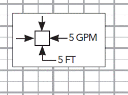
What does the symbol below mean? (this was on the pump curve):

PumpCurveSymbol_baf77p.gif


=====================================
(2B)+(2B)' ?
 
Yeh, I saw that and wondered the same thing....

Duhhh Just figured it out - It's just telling you what each little box on the pump curve is....

It's not a standard format of pump curve. It doesn't have efficiency and it doesn't have power., but then it is trying to show a lot of small pumps on one graph instead of one each.

Capture_pump_tpnnzt.jpg


Remember - More details = better answers
Also: If you get a response it's polite to respond to it.
 
Ha! That's funny. That's pretty obvious in retrospect, although still kind of odd (they would have been better of just omitting that imo).
Thanks for figuring it out, and also for making me feel better in not being the only one confused by that!

=====================================
(2B)+(2B)' ?
 
These small pumps are known to be very sloppy. The performance is all over the place.
We used to build large subs, but had a bunch of small ones like this for emptying pits and such.
We figured that 1 out of 4 would be trash when new.
25% differences in power or performance didn't surprise us.

= = = = = = = = = = = = = = = = = = = =
P.E. Metallurgy, consulting work welcomed
 
Centrifugal pumps draw more current with higher flows. What you observe may simply be caused by having a very long discharge pipe the takes a long time to fill.
 
Yes, 1/2 hp is barely like powering this with a drill.

If you still get trouble then try throttling the discharge a bit to reduce power. After you've cleaned it.

Remember - More details = better answers
Also: If you get a response it's polite to respond to it.
 
At one time I posted a motors forum FAQ with my simple understanding of BHP vs flow behavior for various "centrifugal" pumps: faq237-1543.


I did compute the FHP vs flow curve in my attachment. That particular curve is highest in the middle of the operating flow range and lower on each end. Of course we'd rather know BHP vs flow (rather than FHP vs flow) but I don't have that. My best guess is the qualitative behavior of that BHP curve would be the same (highest in the middle of the operating range. I'm curious if anyone agrees/disagrees with that.

If that is correct, it would match the shape I associate with "mixed flow" pumps. I don't know what is the actual classification of this pump in terms of flow direction, I'd also welcome if anyone can tell me that.


=====================================
(2B)+(2B)' ?
 
In a radial flow pump, the liquid enters at the center of the impeller and is directed out along the impeller blades in a direction at right angles to the pump shaft. This type of pump pump combines the hydraulic design of an end-suction pump with a submersible motor. Submersible pumps are always of the close-coupled type – meaning that the overhung vortex impeller mounts directly on the end of the motor shaft, and the pump casing attaches directly to the motor frame.

1/2 HP is 373 watts. These effluent sump pumps have low efficiencies and probably operate at 35 - 40% efficiencies, then your continuous watts could be as high as 373/0.35 = 1070 watts. But they say the startup draw can be 1.5x-2x the continuous draw, so you might consume up to 2100+ watts. That’s roughly as high as 18.3 Amps.

 
Status
Not open for further replies.
Back
Top